Control and fixing device for the sail of a kite

a technology of control and safety device, which is applied in the direction of toy aircraft, special-purpose vessels, marine propulsion, etc., can solve the problems of affecting the aerodynamics of the wing. , to achieve the effect of simple structure and preventing any risk of tangling

Inactive Publication Date: 2006-03-28
ARNAUD BALLU
View PDF32 Cites 19 Cited by
  • Summary
  • Abstract
  • Description
  • Claims
  • Application Information

AI Technical Summary

Benefits of technology

[0010]The object of the present invention is to achieve a reverse gear re-launch control device, in particular for an inflatable kite wing, of simple structure, preventing any risk of tangling, and without disturbing the control and profile of the wing.

Problems solved by technology

The distance separating the front and rear attachments on the tips of the wing does not in fact produce enough leverage to allow a desirable re-launch to be performed directly in reverse.
Nevertheless, such a device disturbs control of the wing, may cause tangling due to the additional lines floating between the front and rear lines, and needs to be integrated directly at the manufacturing stage.
In addition, when a strong traction is exerted on the rear lines, movement of the front / rear attachments of the wing towards one another may appreciably disturb the shape of the wing and have adverse effects on its aerodynamics.

Method used


Image

  • Control and fixing device for the sail of a kite
  • Control and fixing device for the sail of a kite
  • Control and fixing device for the sail of a kite

Examples


Embodiment Construction

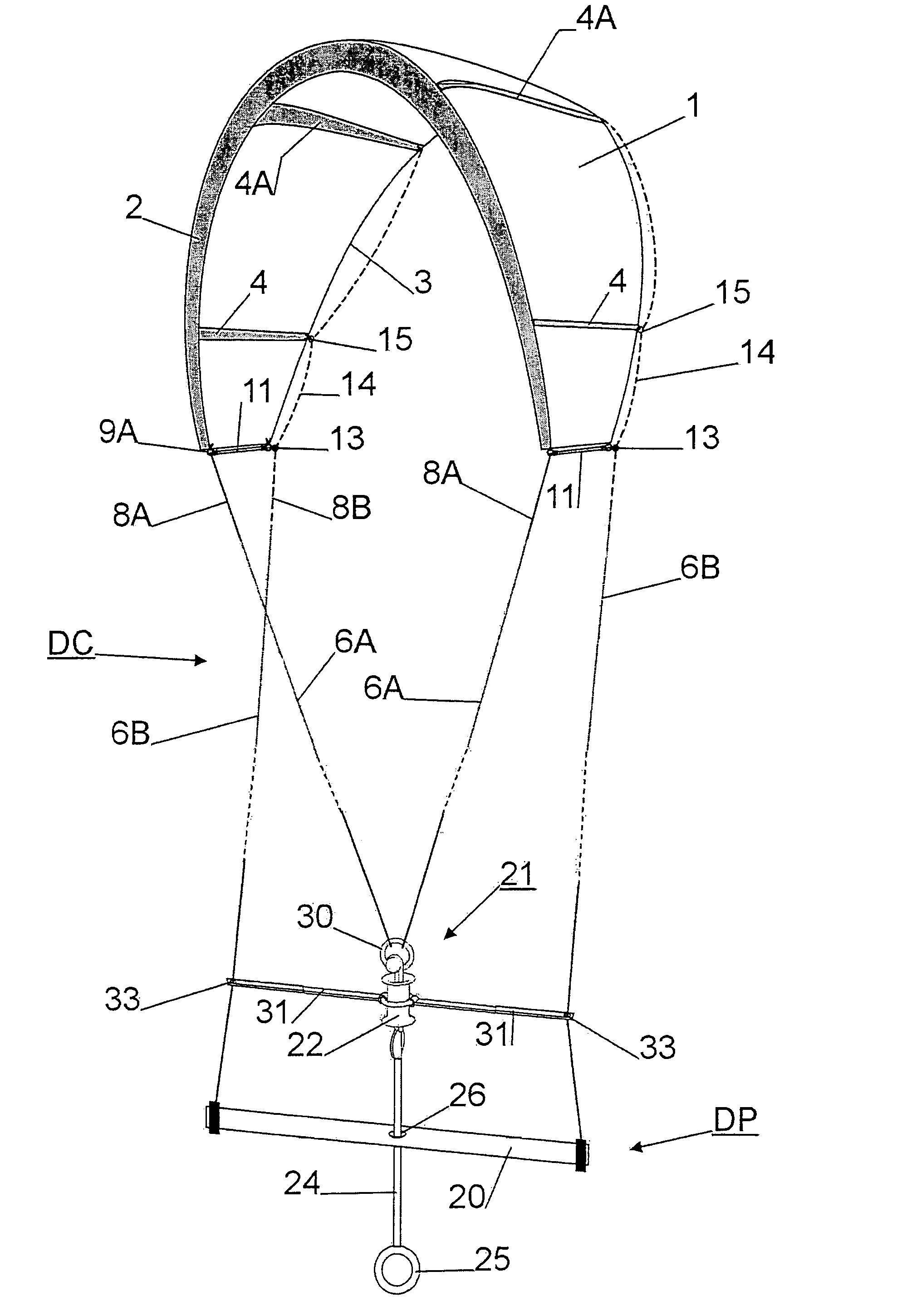
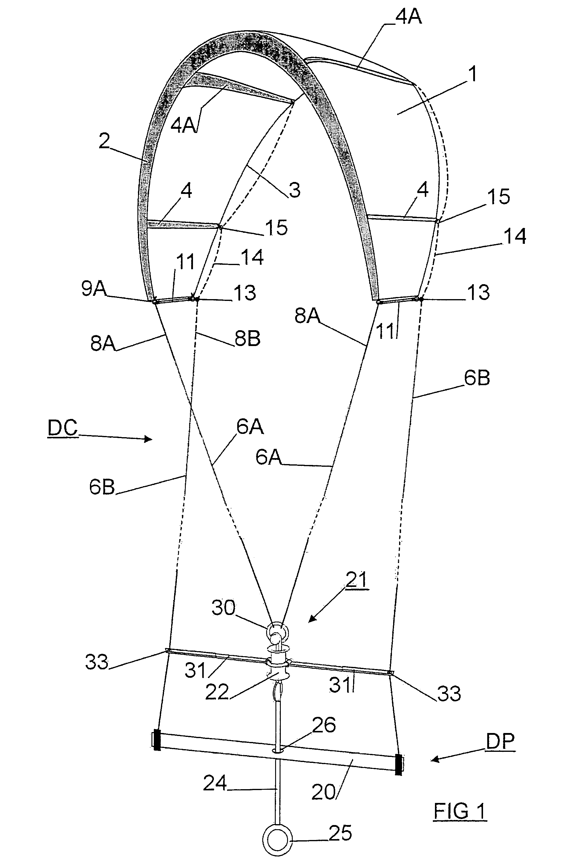
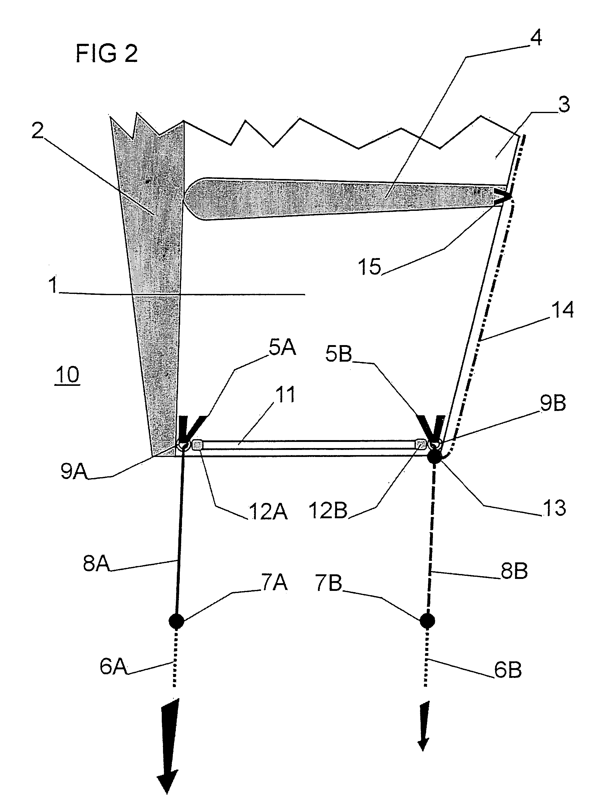
[0019]With reference to FIGS. 1 to 3, the control and safety device DC of a kite wing 1, in particular an inflatable wing, comprises a first pair of front lines 6A, a second pair of rear lines 6B, front attachments 5A and rear attachments 5B, and a control device DP. Each of the two right and left tips of the wing 1 is connected to a front line 6A and to a rear line 6B. The substantially arch-shaped wing 1 is thus equipped with two front lines 6A arranged at the two front tips of the leading edge 2 and with two rear lines 6B arranged at the two rear tips of the trailing edge 3. Only one half of the present device at one of the tips 10 of the wing 1 will henceforth be described in the embodiment of FIGS. 2 and 3. The two sides of the wing 1 are in fact symmetrical and the control device DC that is connected thereto is identical on each side.

[0020]A sliding pre-line 8A runs successively through a link 9A of a front attachment 5A, a stiffening member 11 and a link 9B of a rear attachme...


PUM


Abstract

A control and safety device of a kite wing comprises a stiffening member 11 arranged at each tip of the wing 1 between sliding means 9A, 9B to allow a sliding pre-line 8A to pass through and to maintain a predetermined distance between the front and rear attachments 5A, 5B regardless of the tension applied to the ends of said pre-line.

Description

BACKGROUND OF THE INVENTION[0001]The present invention relates to a control and safety device for a power kite wing, in particular an inflatable wing, comprising:[0002]a first pair of front lines connected to front attachments situated at each tip of the leading edge,[0003]a second pair of rear lines connected to rear attachments arranged at each tip of the trailing edge,[0004]sliding means fixed to the front and rear attachments for the lines to pass through,[0005]and a control device operating in conjunction with the front and rear lines to guide the kite.STATE OF THE ART[0006]Modern arch-shape power kites are usually provided with four control lines, two front and two rear, connected to the four corners of the kite and enabling a turning action and a pitching action. When the kite falls into the water, the configuration is very often recurrent—lines stretched to the leeward of the pilot, kite resting on its front (leading edge) and stuck in this position without being able to be ...

Claims


Application Information

Patent Timeline
Patent Type & Authority Patents(United States)
IPC IPC(8): A63H27/00B63B35/79
CPCB63B35/7979B63B35/7933B63H8/16B63H8/18B63H8/12
Inventor ROYANNAIS, ARIELLEBALLU, ARNAUD
Owner ARNAUD BALLU
Why Eureka
Try Eureka