Compressive end effector

Active Publication Date: 2006-03-28
AMF AUTOMATION TECH
View PDF8 Cites 65 Cited by
  • Summary
  • Abstract
  • Description
  • Claims
  • Application Information

AI Technical Summary

Benefits of technology

[0005]It is therefore an object of the present invention to provide apparatus that is capable of picking a product to form a product bundle, com

Problems solved by technology

This often is undesirable because each object may be squeezed differently from the others in the basket or container.
If all the products are pushed away to make room for an “un-squeezed” last object, then they are squeezed to different degrees which is similarly undesirable.
If the last product is squeezed into the remaining space left over after all the un-squeezed objects are in place, then the last object is squeezed to a different degree which is again

Method used


Image

  • Compressive end effector
  • Compressive end effector
  • Compressive end effector

Examples


Example

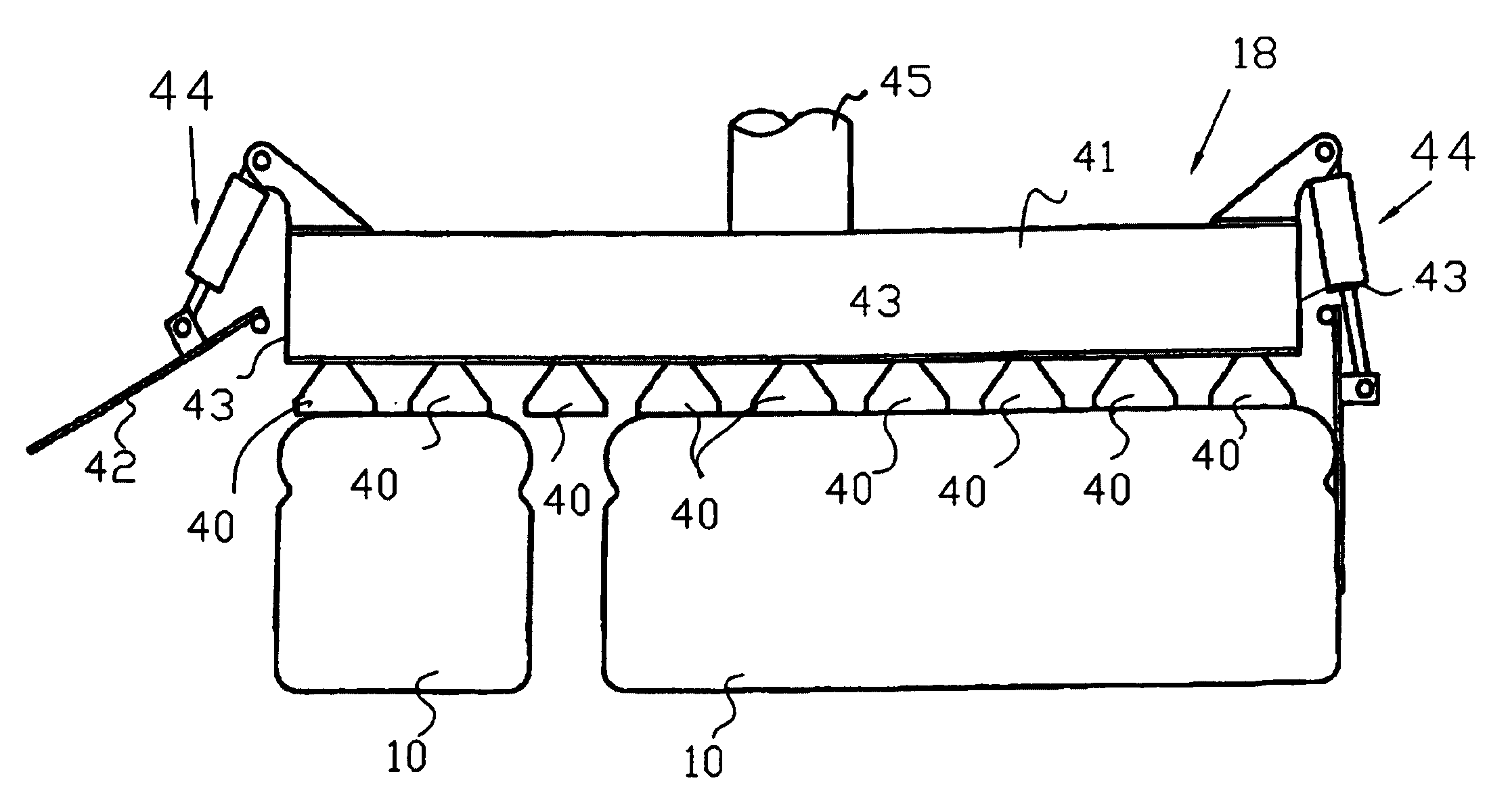
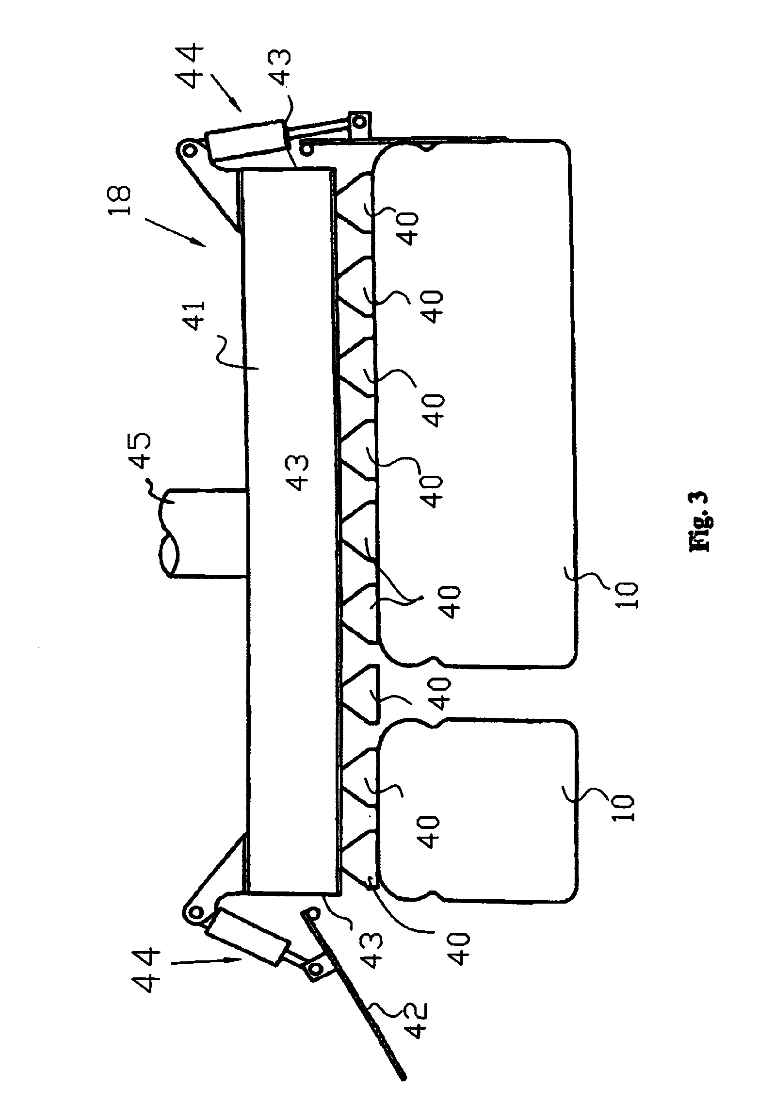
[0016]According to the present invention an uncompressed bundle of product is loosely held from the top with vacuum and at the end of an end effector is simultaneously compressed from all sides at the same time with thin compression plates located about the outer periphery of a vacuum assisted end effector to form an evenly compressed bundle that can then placed in the container with the compression plates between the product and the container walls. The vacuum is then removed; the inward force of the compression plates released and the compression plates removed vertically from between the product and the containers walls. The simultaneous compression from all sides provides even distribution of forces on the product and ensures that all products are compressed or deformed to the same degree. Using the apparatus described herein to place the bottom of the products gently onto the inside bottom of the container is further advantageous.

[0017]Referring now to FIG. 3 that depicts a sch...


PUM


Abstract

Apparatus and method for holding an uncompressed bundle of product from the top with a vacuum assisted end effector and then simultaneously compressing the bundle from all sides at the same time with thin compression plates located about the periphery of a vacuum assisted end effector to form an evenly compressed product bundle that is then placed in a container with the compression plates between the product and the container walls. Once the bundle is received in the container, vacuum is removed; the inward force of the compression plates released and the compression plates removed vertically from between the product and the containers walls. The simultaneous compression from all sides provides even distribution of forces on the product and ensures that all product is compressed or deformed to the same degree. Using the apparatus described herein to place the bottom of the products gently onto the inside bottom of the container is further advantageous.

Description

FIELD OF THE INVENTION[0001]The present invention relates to robotic end effectors for picking products and more particularly to a rotating end effector including peripheral compressive plates that compact product picked by the end effector.BACKGROUND OF THE INVENTION[0002]The use of vacuum assisted picking end effectors to achieve the movement of product is quite common in robotic packaging operations. In many of these automated packaging operations the product being packaged must be assembled into a bundle on the end effector prior to insertion into a suitable container or basket. Such is particularly the case in the packaging of, for example, bakery products or the like, where a bundle of bread loaves or the like are assembled on an end effector and then inserted into a delivery basket or container.[0003]Such a problem is particularly acute in those applications wherein it is required that all of the products designated as a full layer in a container or basket (such as the bread ...

Claims


Application Information

Patent Timeline
IPC IPC(8): B25J15/06
CPCB65G47/91B25J15/0616
Inventor PARNELL, GEOFFREYBOYD, PAULROBINSON, LEEPEARCE, TOM
Owner AMF AUTOMATION TECH
Why Eureka
Try Eureka