Aircraft escape slide lighting system

a technology for aircraft and slide, applied in the direction of landing aids, aircraft ejection means, lighting support devices, etc., can solve the problems of increasing the volume of the slide or raft, increasing the difficulty in packing the unit, and hard plastic housings often break under pressure, so as to achieve the effect of safe protection of leds

Inactive Publication Date: 2006-03-28
ASTRONICS DME LLC
View PDF10 Cites 36 Cited by
  • Summary
  • Abstract
  • Description
  • Claims
  • Application Information

AI Technical Summary

Benefits of technology

[0012]The present invention provides an illumination system for use in aircraft evacuation slides. The illumination device is comprised of a plurality of assemblies, each including one or more light emitting diodes (LEDs) secured to and electrically connected to either a mounting surface or the surface of a printed circuit board. Each assembly

Problems solved by technology

Needless to say, sufficient illumination strength and targeting is essential and often a matter of life or death during aircraft evacuation, whether on land or at sea.
These hard, plastic housings often break under pressure, often occurring when the evacuation slide is folded during non-use.
Further, the hard, unyielding plastic covering of these housings take up additional volume therefore increasing the volume of the slide or raft and increasing the difficulty in packing the unit.
However, none of the systems disclose a lighting system applicable to an aircraft evacuation slide.
Further, the use of a plastic housing to enclose the LED severely limits light transmission, as the light from the LED must first travel through the plastic encasement before reaching its target area.
In an aircraft evacuation scenario, the prior art use of hard plastic housings over the LEDs would seriously increase the probability of system failure since evacuation slides are tightly compressed during storage and the incr

Method used


Image

  • Aircraft escape slide lighting system
  • Aircraft escape slide lighting system
  • Aircraft escape slide lighting system

Examples


Embodiment Construction

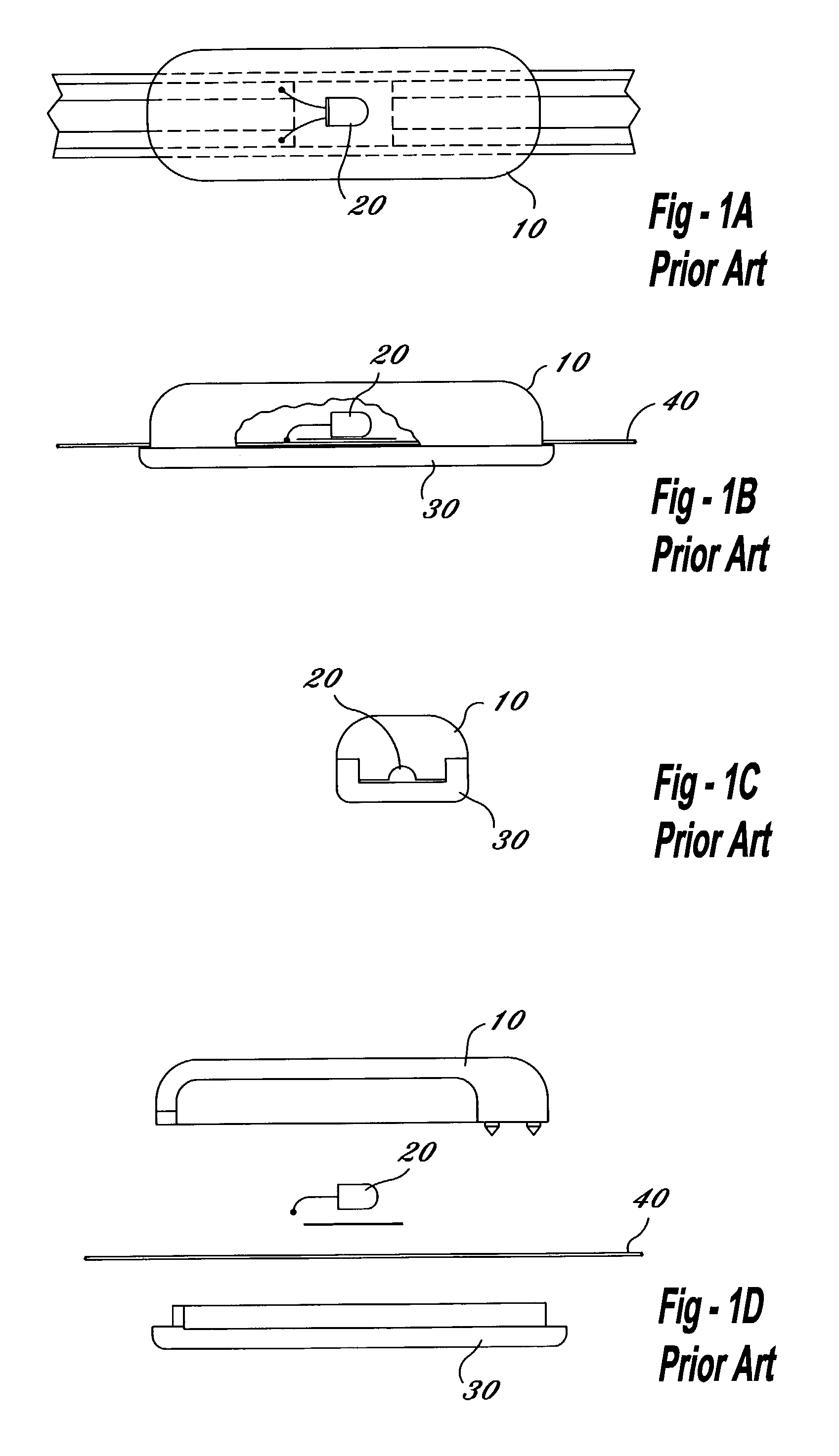
[0049]As seen in FIGS. 1A–1D, an illumination assembly commonly used in the prior art, is shown. A plastic housing 10 encloses the light source 20, a glass incandescent lamp, which is secured to a housing base 30. A 20 AWG conductive wire 40 carries electrical current to light source 20. Plastic housing 10 completely encloses the light bulb 20, leading to a multitude of potential problems. For example, plastic housing 10 can crack, cloud and shatter thereby rendering the illumination assembly inoperable. Plastic housing 10 can shatter under point contact, line contact and bearing loads of only 375 pounds.

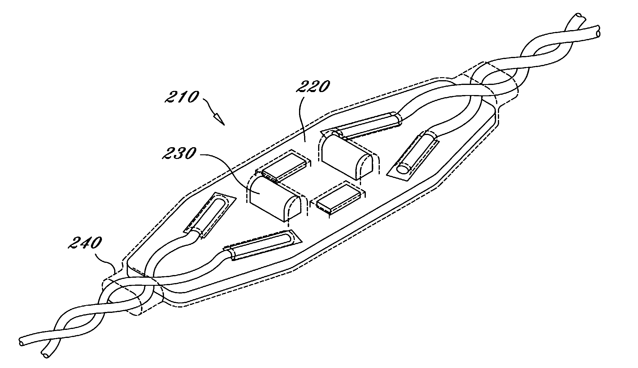
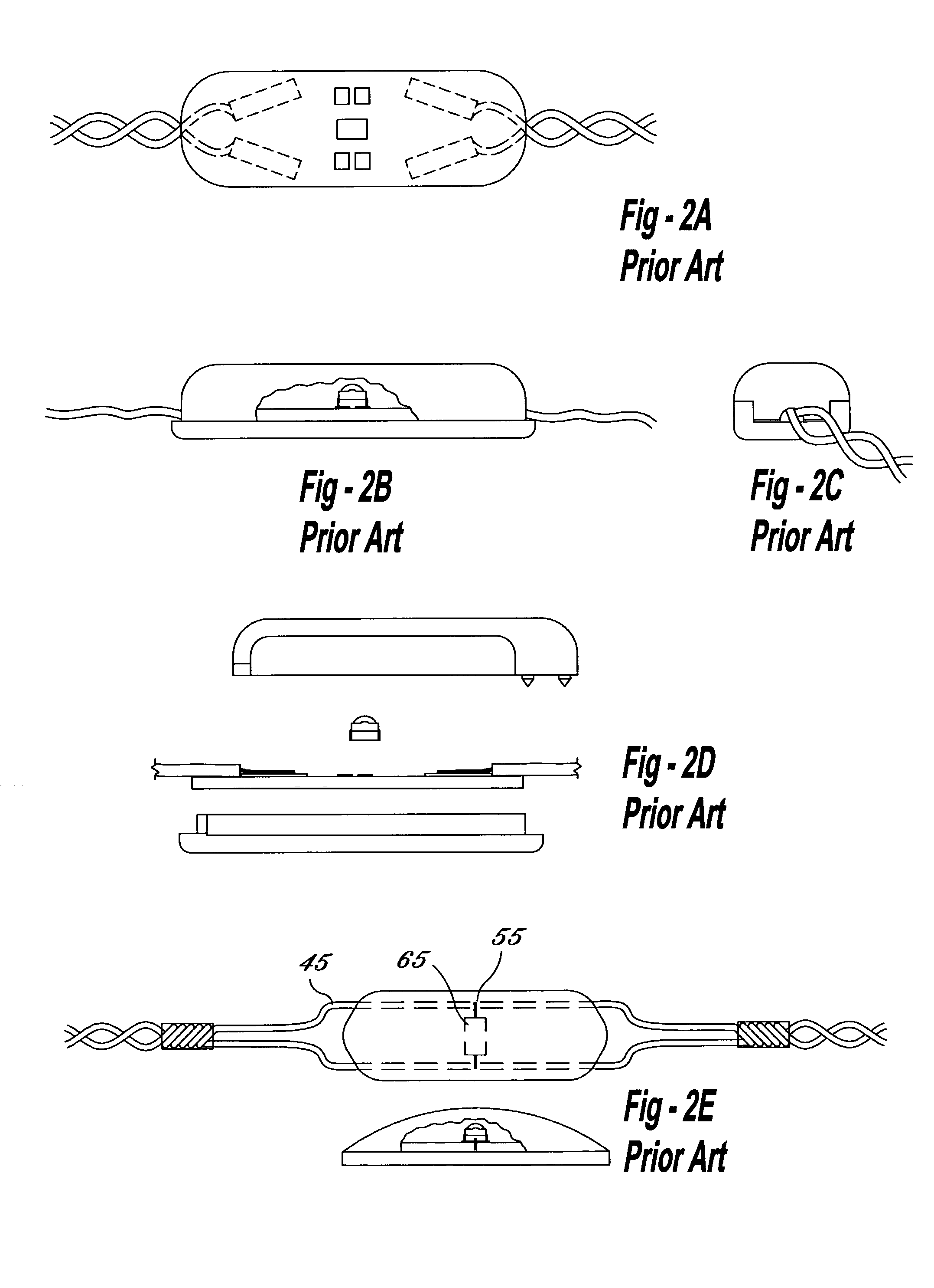
[0050]In FIGS. 2A–2D, another prior art illumination system is shown. In these figures, a housing cover completely covers an LED, which is mounted on a housing base, along with the conductive wire. Once again, due to possible cracking or clouding of the plastic housing or the freezing of moisture within the housing, the evacuation slide and the evacuation area may not be adequately ...


PUM


Abstract

The present invention is a lighting system for providing illumination to an aircraft evacuation slide. Light sources are safely utilized with an existing evacuation slide, a substantial improvement over prior assemblies that use a hard, plastic housing enclosing the light source. The invention increases light transmission, eliminates housing cracking, inadvertent puncturing, clouding, and decreases weight and cost of conventional slide systems. Each assembly comprises a mounting surface and a printed circuit board thereon, light sources, preferably light-emitting diodes (LEDs) mounted on the mounting surface, the light sources illuminating the aircraft evacuation slide, and a flexible containment covering, such as a heat shrink wrap that covers the assembly and protects the light sources. A protective shield can cover the mounting surface while allowing the LEDs to protrude through an aperture in the shield, protecting the LEDs from damaging forces while allowing light to illuminate the landing area.

Description

[0001]This application claims the benefit of and priority to provisional application Ser. No. 60 / 307,210, filed on Jul. 23, 2001.BACKGROUND OF THE INVENTION[0002]1. Field of the Invention[0003]The present invention relates generally to illuminated aircraft evacuation systems and in particular to a lighting system for providing illumination to an aircraft evacuation slide or slide raft that emits more light, is more durable, more dependable and more cost-effective than conventional slide lighting systems.[0004]2. Description of the Prior Art[0005]Aircraft evacuation often occurs at night, or under low light conditions, thus mandating the need for an illumination system to allow occupants of the aircraft to evacuate via an escape slide. Lights are often placed along the evacuation slide perimeter to illuminate the sliding lane area and the end of the slide where the evacuee's feet first touch the ground during an emergency evacuation from an aircraft. Needless to say, sufficient illum...

Claims


Application Information

Patent Timeline
IPC IPC(8): F21V1/20F21V15/00
CPCA62B1/20F21V33/0076B64D25/14B64C2027/8236H05K3/284F21Y2101/02F21Y2115/10B64D2203/00
Inventor FRANCO-VILA, JOSEPELFREY, PHILIPLEVINE, GLENN
Owner ASTRONICS DME LLC
Why Eureka
Try Eureka