Dental implant analog having retention groove for soft tissue modeling

a technology of soft tissue modeling and dental implants, applied in the field of laboratory components, can solve the problem of not having a soft tissue model appropriate location registered on the implant analog or the stone model,

Inactive Publication Date: 2006-03-28
BIOMET 3I LLC
View PDF18 Cites 93 Cited by
  • Summary
  • Abstract
  • Description
  • Claims
  • Application Information

AI Technical Summary

Benefits of technology

[0008]When the implant analog is installed on the impression coping within the impression material, the material for forming the soft tissue model is inserted around the impression coping and the implant analog in the region of this groove so that a rib having a size and shape that generally corresponds to the size and shape of the groove is created in the soft tissue model. Thus, after the stone model and the soft tissue model are developed, the laboratory technician can remove the soft tissue model from the stone model and reinstall the soft tissue model back on the stone model at the precise location. In other words, the groove in the implant analog allows for proper registration of the soft tissue model on the stone model each time the soft tissue model is reinstalled on the stone model.

Problems solved by technology

For example, the laboratory technician may want to visualize the subgingival contours of the dental prosthesis, but cannot do so if the soft tissue model is present.
In prior art implant analogs, however, there is nothing that registers the appropriate location of the soft tissue model on the implant analog or the stone model.
This registration problem is accentuated when the laboratory technician is developing a single tooth restoration having very little surface area between the soft tissue model and the stone model for providing registration and between the soft tissue model and the analog.

Method used


Image

  • Dental implant analog having retention groove for soft tissue modeling
  • Dental implant analog having retention groove for soft tissue modeling
  • Dental implant analog having retention groove for soft tissue modeling

Examples


Embodiment Construction

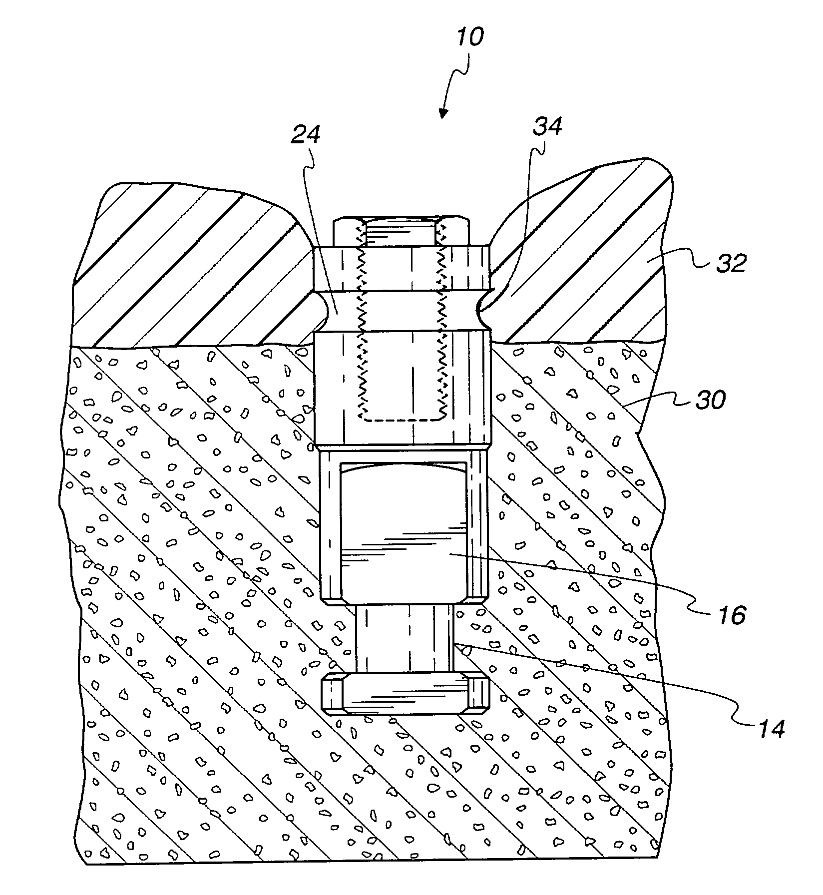
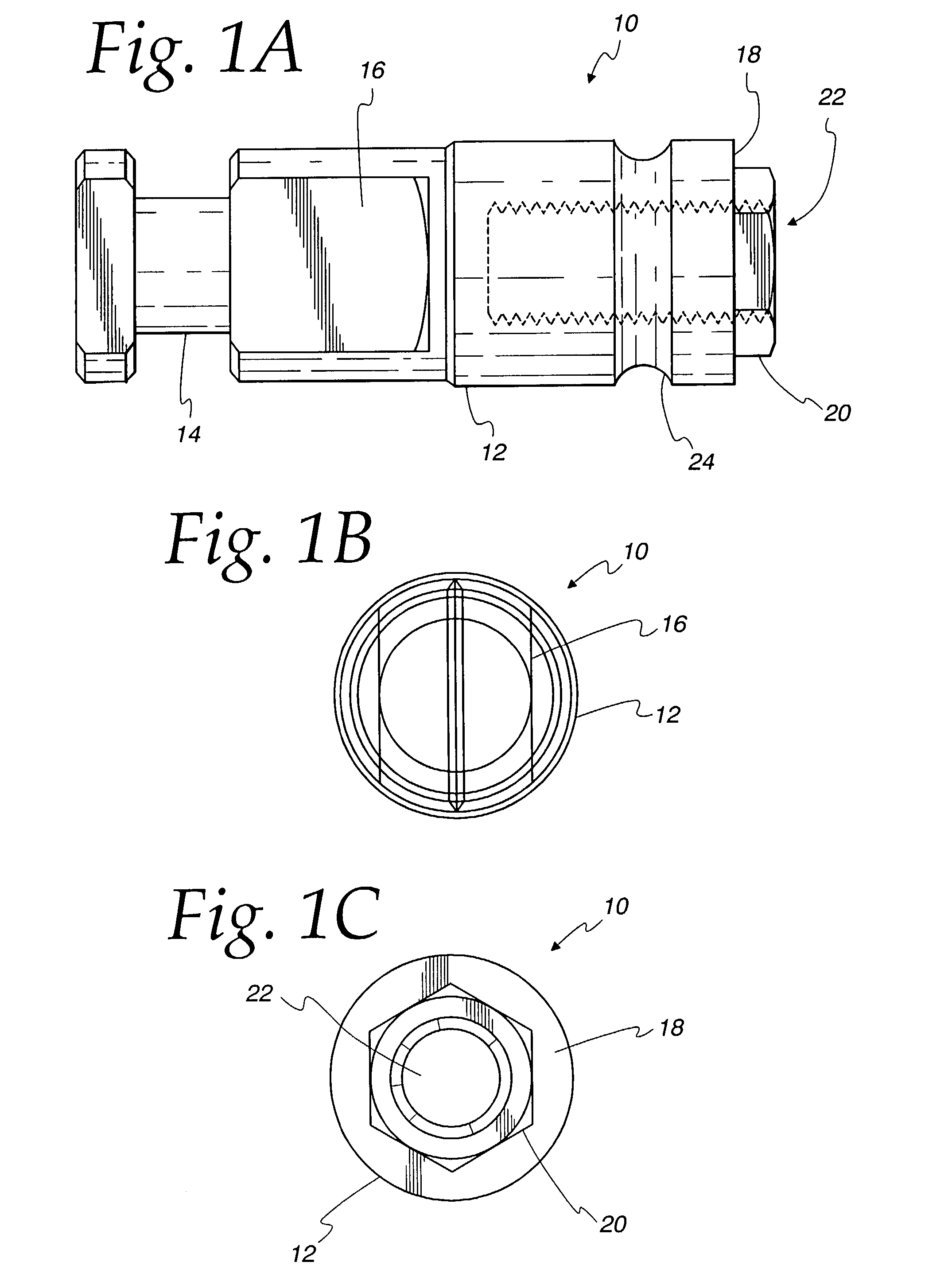
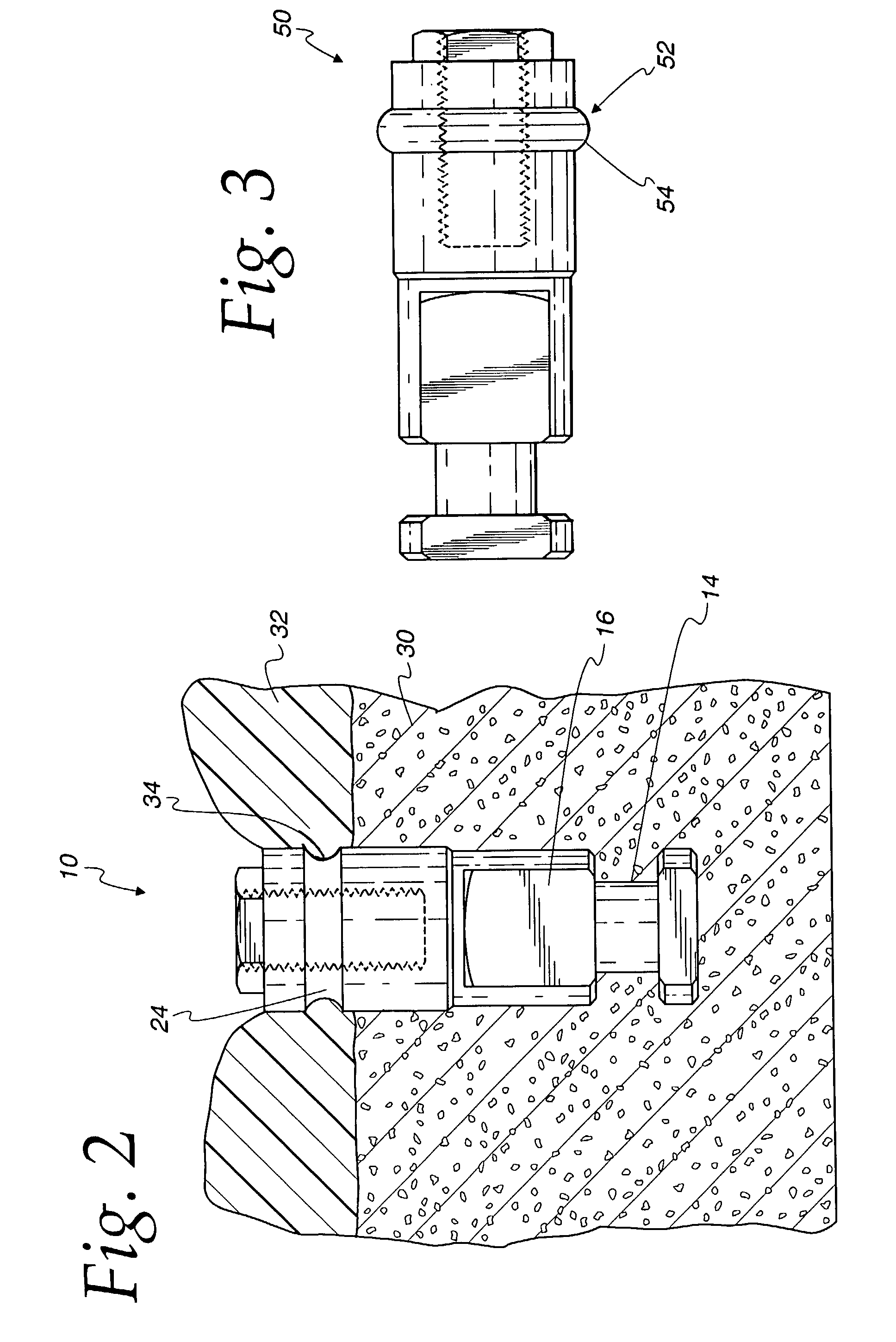
[0018]FIGS. 1A–1C illustrate an implant analog 10 that is to be embedded in a stone model that replicates the prevailing conditions of a mouth of a dental patient. The analog 10 includes a main body 12 that has a lower groove 14 and a flat region 16. The flat region 16 resists rotational movement of the implant analog 10 when it is embedded in the stone model. The lower groove 14 prohibits movement of the implant analog 10 in the axial direction when it is embedded in the stone model.

[0019]The analog 10 includes an upper surface 18 that supports an article that is used by a laboratory to develop a prosthetic tooth. A fitting 20, shown as a hexagonal boss, is located at the upper surface 18. The fitting 20 could also be a polygonal socket that extends into the upper surface 18. A threaded bore 22 extends into the main body 12 of the implant analog 10 and serves to receive a screw that holds the laboratory article on the upper surface 18 of the analog 10. Unlike implant analogs in the...


PUM


Abstract

An implant analog is for supporting an article that is used to develop a dental prosthesis. The analog provides a main body for being anchored in a model of a mouth of a patient. The main body includes an upper surface for contacting the article that is used to develop a dental prosthesis. The analog includes a groove extending inward along a periphery of the main body below the upper surface for receiving a soft modeling material that replicates gingival tissue. Material for forming a soft tissue model flows into the groove to create a corresponding rib in the soft tissue model that allows the soft tissue model to be properly registered on the underlying stone model.

Description

FIELD OF THE INVENTION[0001]The present invention relates generally to laboratory components that are useful for making a dental prosthesis and, in particular, to an implant analog that is useful for holding a soft tissue model on a stone model.BACKGROUND OF THE INVENTION[0002]The dental restoration of a partially or wholly edentulous patient with artificial dentition is typically done in two stages. In the first stage, an incision is made through the gingiva to expose the underlying bone. An artificial tooth root, usually a dental implant, is placed in the jawbone for integration. The dental implant generally includes a threaded bore to receive a retaining screw holding mating components therein. During a typical first stage, the gum tissue overlying the implant is sutured and heals as the osseointegration process continues.[0003]Once the osseointegration process is complete, the second stage is initiated. Here, the gum tissue is re-opened to expose the end of the dental implant. A...

Claims


Application Information

Patent Timeline
Patent Type & Authority Patents(United States)
IPC IPC(8): A61C9/00A61C8/00A61C13/00
CPCA61C8/0001A61C13/0003A61C9/00
Inventor PRESTIPINO, DAVID M.
Owner BIOMET 3I LLC
Why Eureka
Try Eureka