
Vacuum assisted relief system (VARS)

Inactive Publication Date: 2006-03-28
EASTER WILLIAM CRAIG
View PDF34 Cites 188 Cited by
  • Summary
  • Abstract
  • Description
  • Claims
  • Application Information

AI Technical Summary

Benefits of technology

[0022]VARS (Vacuum Assisted Relief System) is an aircrew bladder relief system that allows the pilot, whether male or female, to urinate in flight with comfort and convenience. There are three principle parts to the system, The pump, the garment, and the receiver.
[0024]Comfort for long flights is achieved through a natural interface. The system is attached to the body by belt clip, pocket, or other methods. The system includes barrier creams, an interface that replaces existing undergarments, plastic tubing, pumps, and reservoirs. The system has features that provide for hands free operation and essentially eliminates leakage and drying of the skin. This system has usage across the social spectrum, from astronauts to those confined to wheelchairs.

Problems solved by technology

As a result of the confines of an aircraft, in an aircraft installed embodiment, this may be a worst case scenario.
In addition, there is a practical limit on the pump size based on battery life, physical size, and the amount of vacuum, which can be applied to sensitive areas.
Flow may be unsteady, as only 30% of the holes in the manifold may have contact with urine.
However, most positive displacement pumps require pressure relief systems to prevent damage to the pump or system if a valve is closed or the outlet blocked.
The test results found that values of pressure below 2 PSI will cause slow operation and possible unsatisfactory results.
However, with improved manifold designs (e.g., fewer holes), less vacuum may be acceptable.
There were some sources of error in testing.
Some moisture collects in the tubing with each test that is difficult to account for.
With higher pressure, the water separator is less efficient at separating the water out as some fluid is noted entering the flow meter.
The most likely point of failure was the ability of the fluid to pass from the body to the garment to the pump.

Method used


Image

  • Vacuum assisted relief system (VARS)
  • Vacuum assisted relief system (VARS)
  • Vacuum assisted relief system (VARS)

Examples


Embodiment Construction

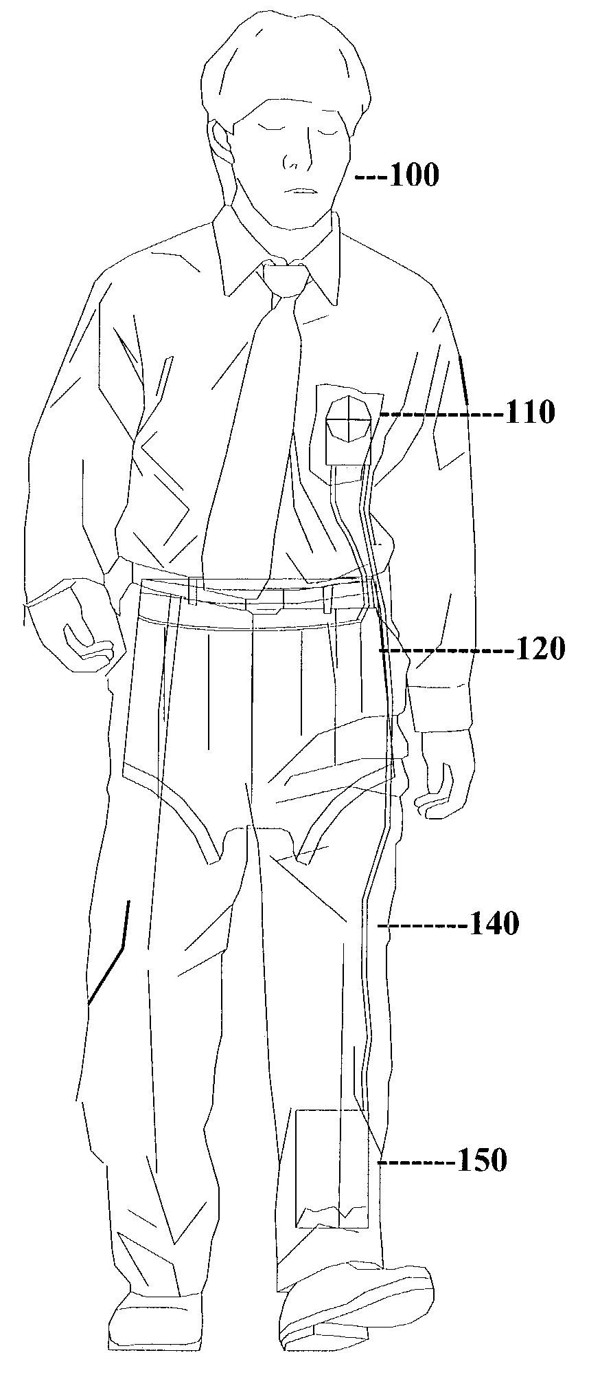
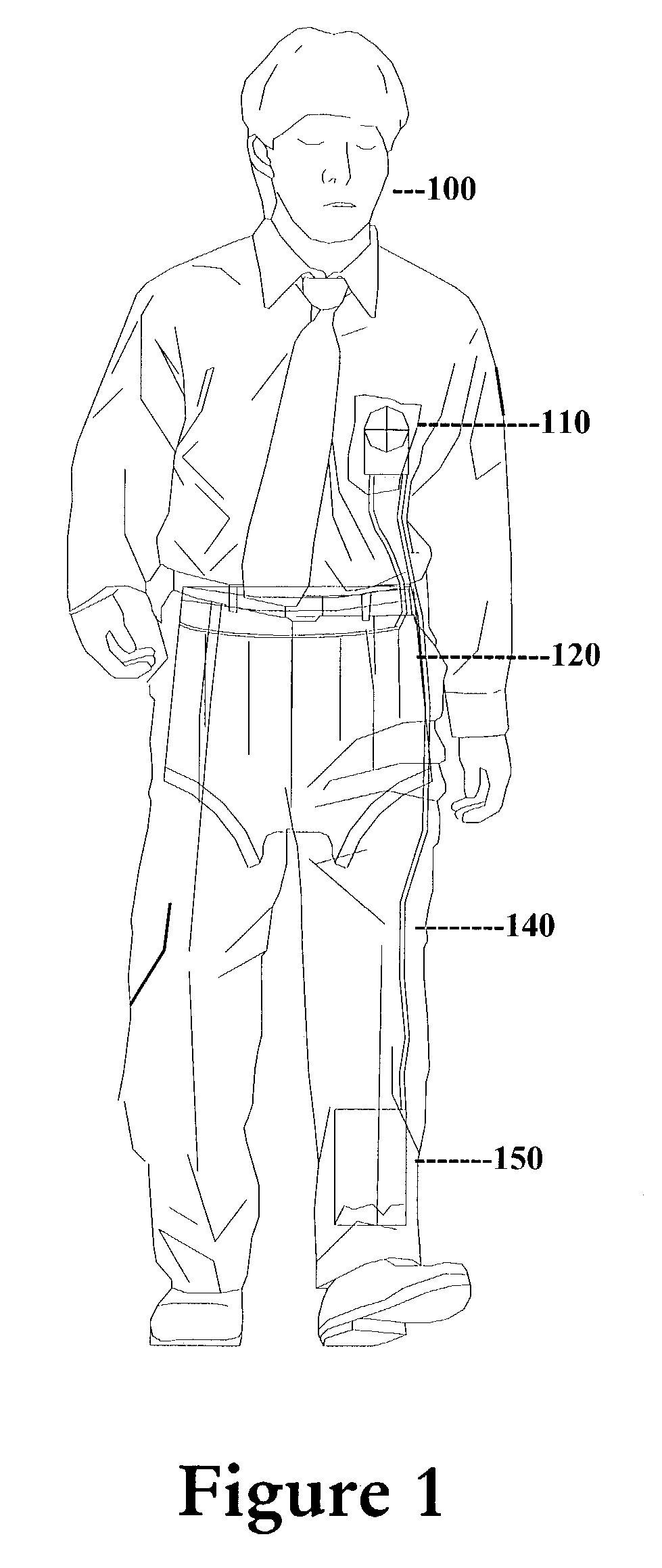
[0036]FIG. 1 is a perspective exposed view of the apparatus of the present invention as mounted on a user 100. In this civilian embodiment, pump and battery pack 110 is illustrated mounted in a breast pocket or attached to a torso harness at breast level. Locating the pump at a level higher than the garment insures little or no “leak back” to the garment.

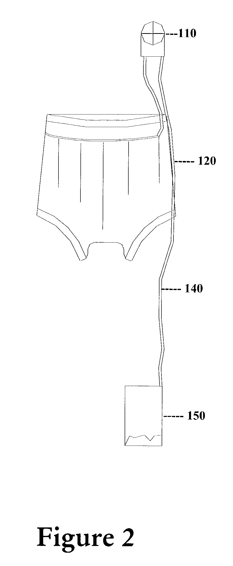
[0037]Garment 120, as will be described in more detail below, includes an intake manifold comprised of a number of perforated tubes sandwiched between layers of material. Urine from user 100 is collected in the garment, drawn into the manifold tubes through these holes, by means of vacuum from pump 110. Collected urine then passes through hose 140 into containment bag or receiver 150. FIG. 2 is a perspective front view of the components of FIG. 1.

[0038]In a military application, the apparatus may be partially mounted to a survival vest such as a P / N LPU-10 / P MIL-38484 United States Air Force (USAF) and pump / battery pack 110 may be i...


PUM


Abstract

VARS (Vacuum Assisted Relief System) is a aircrew bladder relief system that allows the pilot, whether male or female, to urinate in flight with comfort and convenience. There are three principle parts to the system, The pump, the garment, and the receiver. A pump and battery pack may be mounted in a breast pocket or attached to a torso harness at breast level. Locating the pump at a level higher than the garment insures little or no “leak back” to the garment. A garment worn like a diaper or underwear, includes an intake manifold comprised of a number of perforated tubes sandwiched between layers of material. Urine from a user is collected in the garment, drawn into the manifold tubes through these holes, by means of vacuum from the pump. Collected urine then passes through a hose into containment bag or receiver.

Description

FIELD OF THE INVENTION[0001]The present invention relates to relief system for containing and removing urine or other human (or animal) waste from the body. In particular, the present invention is directed toward an undergarment provided with a vacuum pump for removing urine and the like from a human or animal. The present invention may also be used to drain wounds and the like.BACKGROUND OF THE INVENTION[0002]In general aviation (GA) and military aviation it is often not practical to provide restroom facilities on an aircraft due to weight, space, and cost concerns. Pilots and passengers in GA and military aircraft may be subjected to long flying legs or missions without the availability of restroom breaks. If a pilot or passenger has to urinate, it can be a distracting and dangerous condition, as it diverts attention away from flying the aircraft. Moreover, needs exist in other arts to provide devices for absorbing urine from children, incontinent adults, animals, hospital patient...

Claims


Application Information

Patent Timeline
IPC IPC(8): A61M1/00A61F5/451
CPCA61F5/451
Inventor EASTER, WILLIAM CRAIG
Owner EASTER WILLIAM CRAIG
Learn More