LED lamp for light source of a headlamp

a technology of led lamps and light sources, applied in the direction of discharge tubes, luminescnet screens, fixed installations, etc., can solve the problems of inability to meet light distribution characteristics and the like, and achieve the effect of accurate and easy to achiev

Inactive Publication Date: 2006-03-28
STANLEY ELECTRIC CO LTD
View PDF5 Cites 67 Cited by
  • Summary
  • Abstract
  • Description
  • Claims
  • Application Information

AI Technical Summary

Benefits of technology

[0008]As a tangible means of resolving the problems known in the prior art, the present invention realizes an LED lamp for a light source of a headlamp characterized in that an LED chip or a white LED light emission portion comprising an LED lamp and fluorophor is disposed in the vicinity of the focus of a projection means, and a shielding member covering a portion of the white LED light emission portion is provided in a formation allowing a light distribution characteristic suitable for a vehicle headlamp to be obtained when light from the white LED light emission portion is magnified and projected in an illumination direction by the projection means. Accordingly, the problems are resolved by enabling the regulated light distribution characteristics to be accurately and easily achieved even when an LED lamp is used as a light source.

Problems solved by technology

Consequently, problems exist in that light distribution characteristics and the like cannot be satisfied by simply replacing the lamp with an LED lamp radiating light in a single direction in a relatively large amount.

Method used


Image

  • LED lamp for light source of a headlamp
  • LED lamp for light source of a headlamp
  • LED lamp for light source of a headlamp

Examples


Embodiment Construction

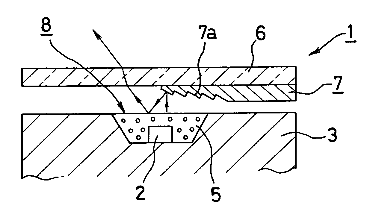
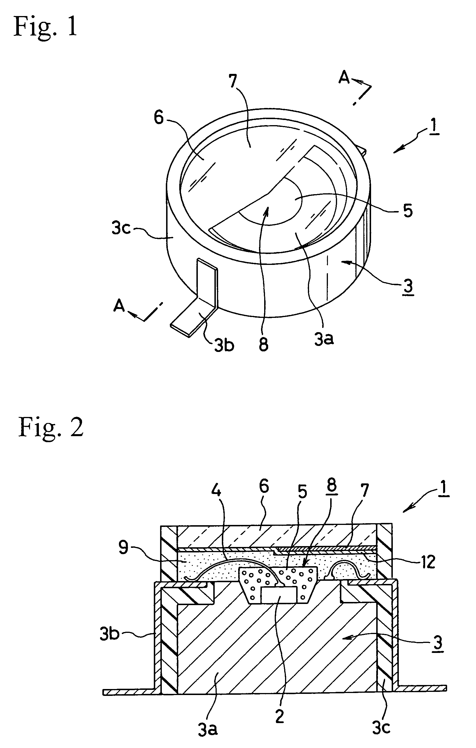
[0037]Hereinafter, the present invention will be described by way of preferred embodiments thereof with reference to the accompanying drawings. The part indicated by reference 1 in FIG. 1 and FIG. 2 is an LED lamp for a light source of a headlamp according to the present invention (hereinafter referred to as an “LED lamp 1”), and in the LED lamp 1, an LED chip 2 is mounted on a base unit 3.

[0038]The base unit 3 provides a base 3a formed with a metal member of copper or some other metal excellent in heat conduction and a lead frame 3b also formed with a metal member. The base 3a and the lead frame 3b are insulated by an insulating layer 3c formed with a resin member or another similar insulating member. The LED chip 2 mounted on the base 3a is wired to the lead frame 3b using a metal wire 4 or the equivalent, so the lighting can be carried out using power supplied from the exterior.

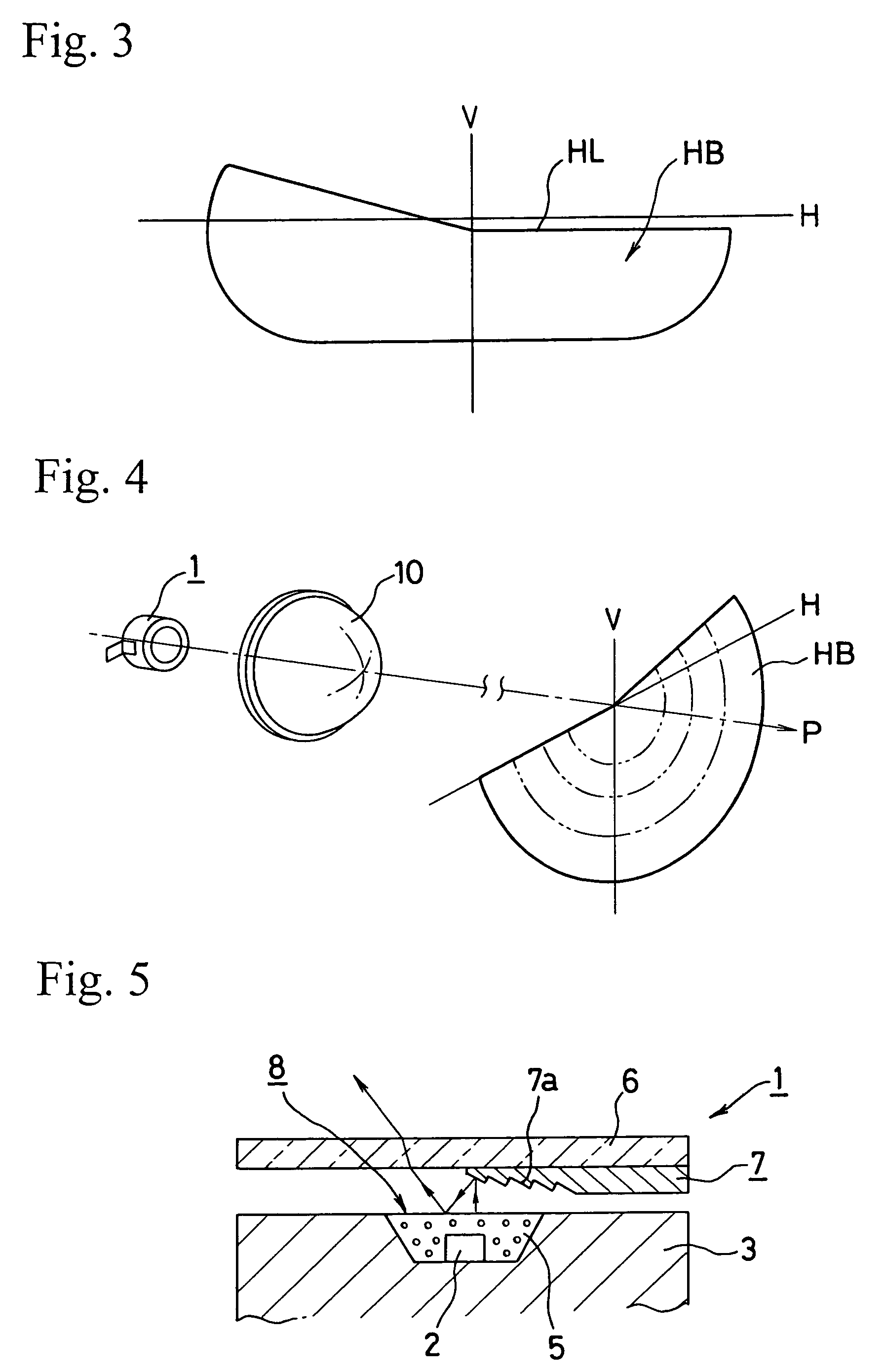
[0039]Considering the conditions to be satisfied for usage of the LED lamp 1 as a light source for a he...


PUM


Abstract

Whereas incandescent light bulbs and other similar light sources known in the prior art emit light in all directions, LED lamps emit light in a single direction only, and this is manifested in the problem of being unable to achieve light distribution characteristics satisfied by conventional headlamp designs. The present invention realizes an LED lamp for a light source of a headlamp disposing an LED chip 2 in the vicinity of the focus of a projection means and providing a shielding member 7 covering a portion of the LED chip 2 in a formation allowing a light distribution characteristic suitable for a vehicle front-illumination light to be obtained when light from the LED chip 2 is magnified and projected in an illumination direction by a projection lens 10 or the like constituting the projection means; accordingly, accurate light distribution characteristics can be obtained in a simple manner by projecting in the illumination direction using the projection lens 10.

Description

BACKGROUND OF THE INVENTION[0001]1. Field of the Invention[0002]The present invention relates to LED lamps, and in particular, to the configuration of LED lamps used as light sources in vehicle lights. Furthermore, it relates to the configuration of an LED lamp suitable for use as a light source in a vehicle lamp for illumination purposes that has not previously been put to use as headlamps (or headlights), auxiliary headlamps (or fog lights), or the like.[0003]2. Detailed Description of the Prior Art[0004]When LED lamps are used as a light source in flashlights and other similar lamps for the purpose of illumination in the prior art, a large LED chip is housed in a large package and light amount is obtained by, for example, applying a current of between several ten and several hundred milliamperes. Simultaneously, as the package is made large in size, deterioration or breakage of the LED chip as a result of overheating is prevented by effectively conducting the heat emitted in the ...

Claims


Application Information

Patent Timeline
Patent Type & Authority Patents(United States)
IPC IPC(8): H01L29/22H01J1/62F21S8/10F21V11/00F21V11/16F21W101/10F21Y101/02H01L33/42H01L33/50H01L33/56H01L33/58H01L33/60H01L33/62
CPCF21K9/00H01L33/58F21S48/1145H01L2224/45144F21S48/115F21S48/145F21Y2101/02H01L33/52H01L33/60H01L2224/48091H01L2924/19107H01L2924/3025H01L2224/48465H01L2924/00014H01L2924/00F21S41/141F21S41/16F21S41/43F21Y2115/10H01L2924/181H01L2924/00012
Inventor YATSUDA, YASUSHIEBISUTANI, TAKASHIKOIKE, TERUOKUSHIMOTO, TAKUYAOWADA, RYOTAROOHNO, MASAFUMIFUTAMI, TAKASHI
Owner STANLEY ELECTRIC CO LTD
Why Eureka
Try Eureka