
Electronic system with a multiple access protocol and method of multiple access

a technology of multiple access and electronic system, applied in the field of electronic systems, can solve the problems of comparatively long so-called latency time for accessing a unit to the network, high network size,

Inactive Publication Date: 2006-03-28
ROBERT BOSCH GMBH
View PDF3 Cites 5 Cited by
  • Summary
  • Abstract
  • Description
  • Claims
  • Application Information

AI Technical Summary

Benefits of technology

[0011]It is an object of the present invention to provide an improved electronic system of the above-described type, especially an improved security system, with a multiple access protocol for units, devices or sets of the system to a network, in which the above-described disadvantages are at least reduced.
[0016]The claimed electronic system and method of access according to the invention provides an improved electronic system, especially an improved security system, which combines a band-width-efficient use of the network with a short latency time and a reliable access of the individual units to the network.
[0022]The invention has the special advantage that the number of concurrent time slots can be reduced based on the intelligent assignment of the units of the electronic system to different groups. Thus either bandwidth may be saved or the latency time for access to the network may be drastically reduced.

Problems solved by technology

This however is disadvantageous because the bandwidth of the network must be high in order to achieve a short access time, since all the units must have a dedicated time slot in each time frame.
The so-called latency time for access of a unit to the network thus becomes comparatively long when the bandwidth of the network is insufficient.

Method used


Image

  • Electronic system with a multiple access protocol and method of multiple access
  • Electronic system with a multiple access protocol and method of multiple access
  • Electronic system with a multiple access protocol and method of multiple access

Examples


Embodiment Construction

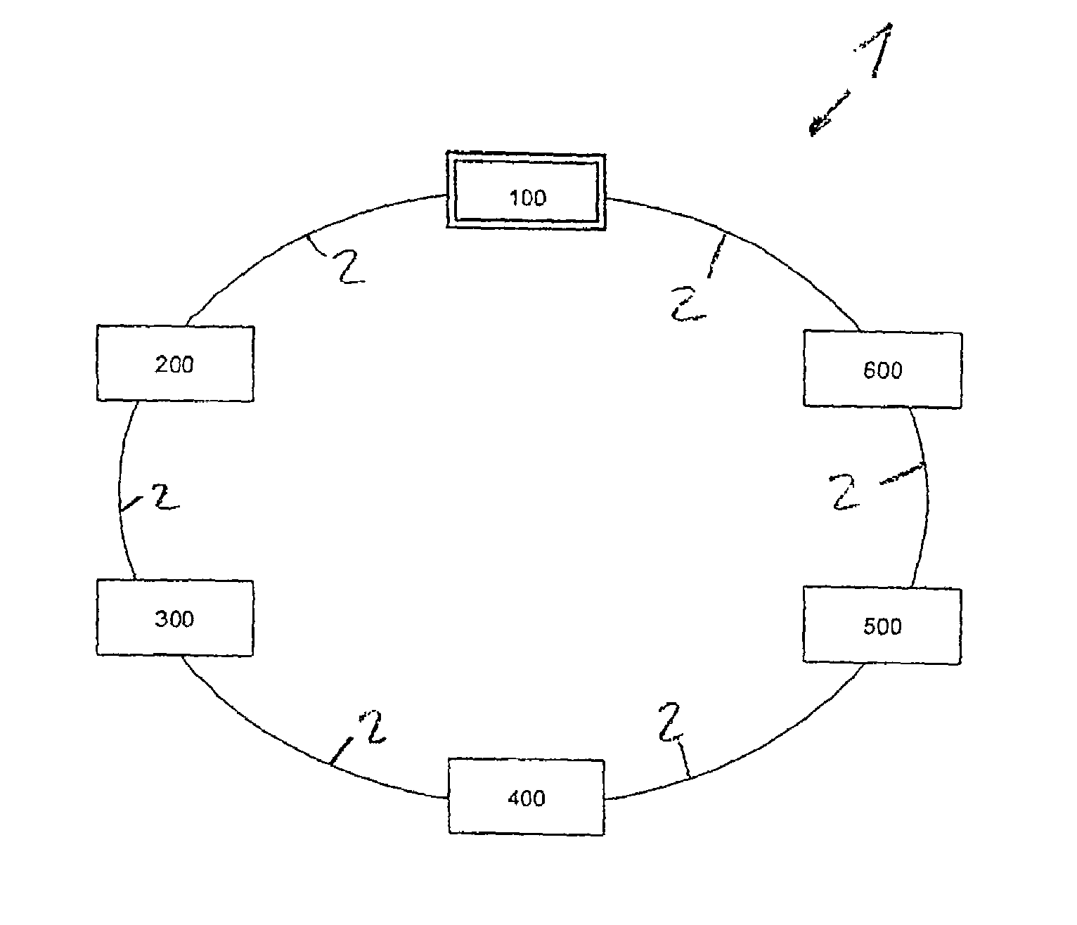
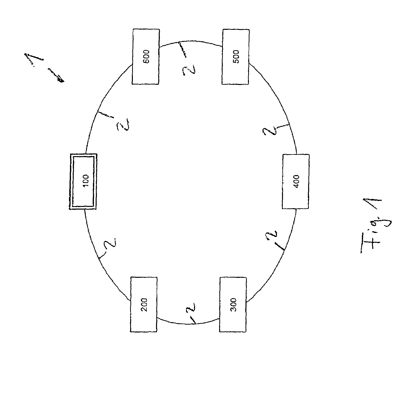
[0032]FIG. 1 shows a network 1 with a central unit 100 and additional units 200 to 600, which are connected in a network by lines 2. The additional units 200 and 500 are fire alarm units and the units 300 and 600 are burglar alarm units or break-in detection alarm units. The unit 400 is a unit for transfer of signals to and from a telephone network. The fire alarms 200 and 500 are widely separated from each other in different parts of a building or other structure.

[0033]After activation of the electronic system according to FIG. 1 the central unit first performs an initialization phase for auto-configuration. All the additional units 200 to 600 are interrogated during this initialization phase.

[0034]Each of the additional units 200 to 600 is assigned a different address in the network 1. Furthermore the central unit 100 measures the signaling time from the central unit 100 to the concerned unit, in order to establish network topology. Then each of the units 200 to 600 signals its ty...


PUM


Abstract

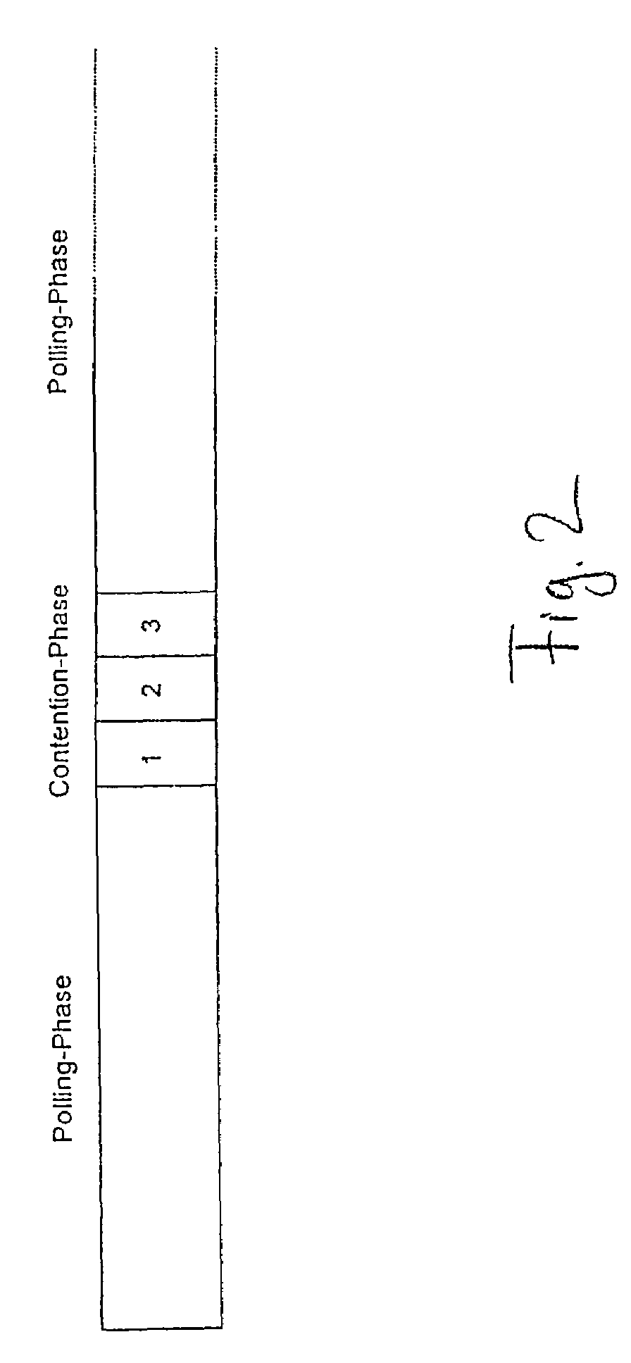
The electronic system, especially a security system, includes a number of different units that access a network according to a multiple access protocol, which is designed to minimize collisions between frames while reducing bandwidth requirements. The units may monitor different spatial regions according to several different criteria. Respective units that monitor according to correspondingly different criteria in a given spatial region may be assembled into one group and units that monitor different spatial regions but according to the same criterion may be assembled into another group. Each of the units of the one group are provided access to the network in one concurrent time slot, while the units of the other group are provided access to the network in a different concurrent time slot.

Description

BACKGROUND OF THE INVENTION[0001]1. Field of the Invention[0002]The present invention relates to an electronic system comprising a plurality of units, devices or sets, which access a network by means of a multiple access protocol and also relates to a suitable method for multiple access to the network and to a computer program for performing the method for multiple access.[0003]2. Description of the Related Art[0004]Different multiple access protocols are known in the state of the art. A review of the different multiple access protocols is provided in “Computer Networks” by Andrew S. Tannenbaum, Prentice Hall, 1998, especially chapter 4.2, pp. 272 and following.[0005]In the so-called ALOHA system the channel assignment occurs so that different users are uncoordinated during concurrent use of a single channel. Pure ALOHA and subdivided ALOHA should be distinguished from each other; in a pure ALOHA method there can be collisions between frames during multiple access. However because o...

Claims


Application Information

Patent Timeline
IPC IPC(8): G08B23/00H04L12/24H04L12/403H04L12/413H04L12/43H04L29/12
CPCH04L12/403H04L12/43H04L61/2038H04L29/12254H04L41/12H04L61/5038
Inventor VOLLMER, VASCODETLEFSEN, WOLFGANG
Owner ROBERT BOSCH GMBH
Learn More