
Page composition in an image reproduction system using segmented page elements

a page composition and image reproduction technology, applied in the direction of visual presentation using printers, electric digital data processing, instruments, etc., can solve the problems of inability to combine page elements which are compressed e.g. using different jpeg formats, visible distortion, and extra loss of image quality

Active Publication Date: 2006-03-28
PUNCH GRAPHIX INT
View PDF12 Cites 27 Cited by
  • Summary
  • Abstract
  • Description
  • Claims
  • Application Information

AI Technical Summary

Benefits of technology

[0005]It is an object of the present invention to provide a method for merging several page elements and delivering page printing data to the printing engine in a digital printing system avoiding the drawbacks of the methods known so far.
[0007]It is another object of the invention to provide a file format enabling easy merging of page elements.
[0008]It is a further object of the invention to provide an easy method for enabling the use of various compression methods and resolutions.
[0010]It is a further object of the invention to provide a method enabling a variety of image operations (rotation, clipping, merging, translation . . . ) without previous computation or the need for storing the same page element twice.

Problems solved by technology

Such an adjustment can be done while keeping exact registering of the boundaries of the different page elements because the locations of the boundaries are stored independently of the image content of the page elements, but the image of the page element is also translated which can cause problems when the images of two continuous tone page elements need to be in exact registration.
In a 300 pixel per inch system (12 pixels / mm) using 8×8 JPEG coding this can lead to shifts of ⅓ mm which can give rise to visible distortions when printing certain images.
For instance, merging of page elements which are compressed e.g. using different JPEG formats is not possible in compressed format.
The image information of these blocks is compressed twice, leading to extra loss of image quality.
Also other drawbacks of the known methods exist.
It is difficult to merge two different page elements having a different resolution.

Method used


Image

  • Page composition in an image reproduction system using segmented page elements
  • Page composition in an image reproduction system using segmented page elements
  • Page composition in an image reproduction system using segmented page elements

Examples


Embodiment Construction

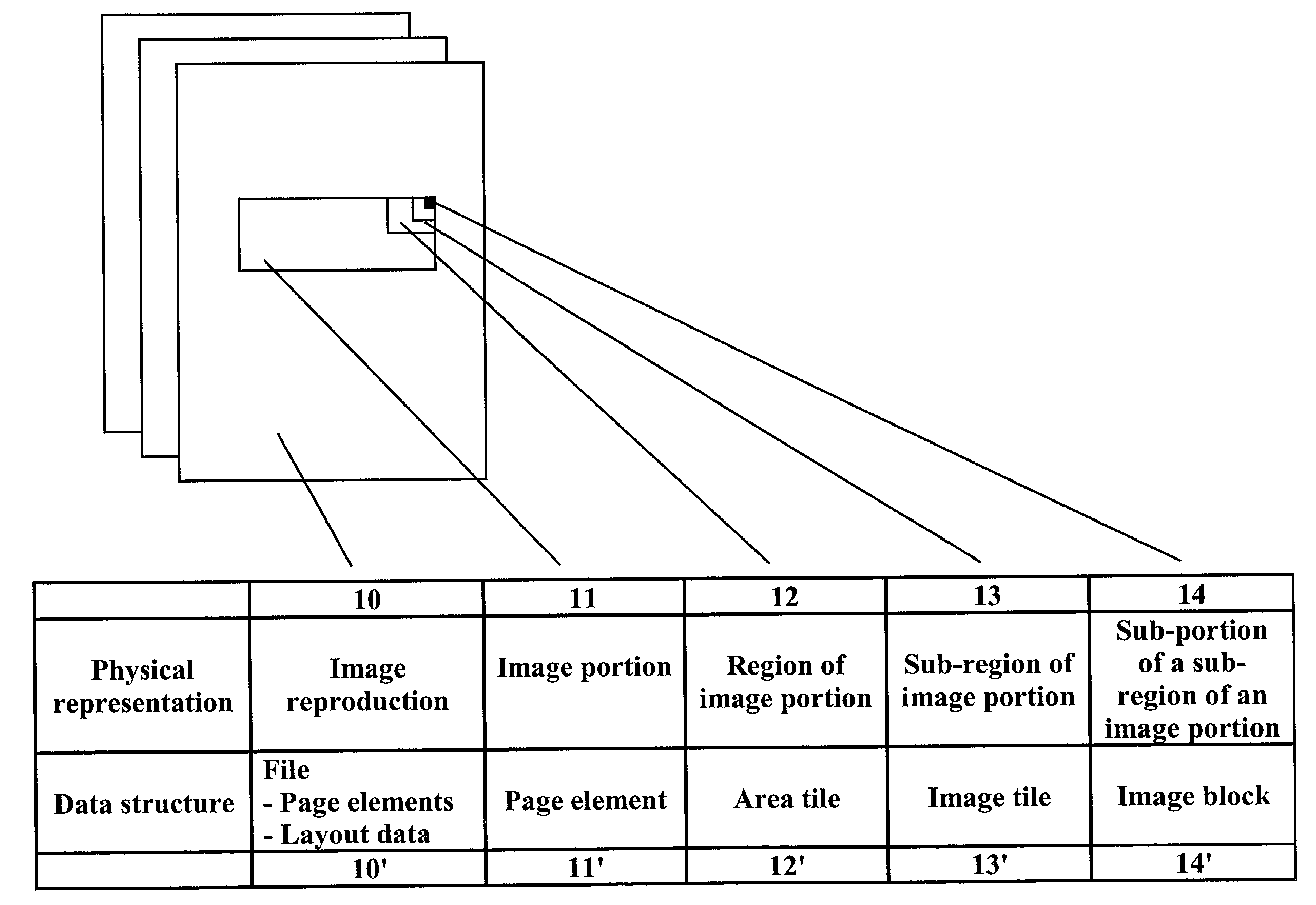
[0047]Hereinafter the different terms, used throughout the specification and claims to better define the present invention and more clearly distinguish it from the prior art, are explained in relation to FIG. 1.[0048]An image reproduction 10 is a reproduction of the image to be produced. This image can include continuous tone image data as well as line-work data such as text, graphics, or artificially created images. The image reproduction 10 may be a physical reproduction printed out by a printing apparatus such as a digital printing apparatus. The image reproduction 10 can also be displayed as an image on a screen. The image reproduction 10 may also take the form of an electronic reproduction such as a file representing the image and which can be used for further processing. An example of such an electronic reproduction is a file stored in a “tagged image file format” (TIFF File).[0049]An image signal is a signal provided to a printer, display device or other means. The image sign...


PUM


Abstract

The invention relates to a method and apparatus for merging page elements according to a layout signal into one page for reproduction on a reproduction device. The page elements are segmented into smaller segments before storage into memory. Due to the particular format of the page elements, data required for the merging of page elements can be retrieved, decompressed an processed quickly so merging can be done in real time during printing. The format used for the segments enables easy and fast execution of various image operations such as mirroring, clipping, rotation, etc . . .

Description

FIELD OF THE INVENTION[0001]The present invention relates to a method and apparatus for composing an image signal for an image reproduction. More specifically the invention is related to a method for merging segmented page elements in real-time to thereby generate an image signal which may be delivered to a reproduction system such as e.g. a printer or a copier.BACKGROUND OF THE INVENTION[0002]Several systems are known to deliver printing data to the printing engine of a digital printing system. A stringent requirement is that the system has to apply a method capable of delivering data at the speed of the printing system.[0003]One such method is described in the international patent application WO-A-99 / 24933. This document relates to the merging of compressed raster images in a printing system capable of printing pages containing variable information with unrestricted variability from page to page. Each page is composed of several page elements which are processed by the raster imag...

Claims


Application Information

Patent Timeline
IPC IPC(8): G06F15/00G06K15/02
CPCG06K15/02G06K15/1863G06K15/1851G06K2215/0065
Inventor DELHOUNE, MARCDIELTJENS, VEERLESUYS, DOMINIQUEBAETEN, ROGER
Owner PUNCH GRAPHIX INT
Learn More