Method for operating a data network

a data network and data technology, applied in the field of data network operation, can solve the problems of data transmission in the data network, failure of the entire communication, and failure of the entire data network operation,

Active Publication Date: 2006-03-28
VOLKSWAGEN AG
View PDF7 Cites 0 Cited by
  • Summary
  • Abstract
  • Description
  • Claims
  • Application Information

AI Technical Summary

Benefits of technology

[0021]It is clear that the master network subscriber can arrange for the transmission links to be checked independently of each other and in particular simultaneously together.
[0022]Expediently the transmitter of a transmission link to be checked can be scaled with respect to its transmitting power. That is, the transmitting power of the transmitter can be set. This design makes it possible to control the transmitting power in the vicinity of the transmission link. Correspondingly the receiver of the transmission link to be checked can also be scaled with respect to its sensitivity in order to implement a control of the receiver sensitivity as a function of the level reserve.

Problems solved by technology

Flawless operation of the entire data network is possible only when all of the individual transmission links are capable of functioning flawlessly.
The failure of a single ring segment, thus a single transmission link, leads to the failure of the entire communication.
The data transmission in the data network can be disrupted, for example, by means of an external event, for example a cable break.
However, a fault can also occur, as the attenuation of the signal transmission within the transmission path gradually increases owing to the ageing phenomena of individual components, such as the transmitter and the receiver.
As soon as the attenuation becomes too high, the signal can no longer be transmitted properly.
However, the prior art method cannot distinguish with respect to the cause of the error between an external event and an ageing phenomena, because as soon as the data transmission no longer functions properly, a corresponding error signal is generated.
On the contrary, maximum signal transmission could even result in an overloading of the receiver, thus also impairing the signal transmission.

Method used


Image

  • Method for operating a data network
  • Method for operating a data network
  • Method for operating a data network

Examples


Embodiment Construction

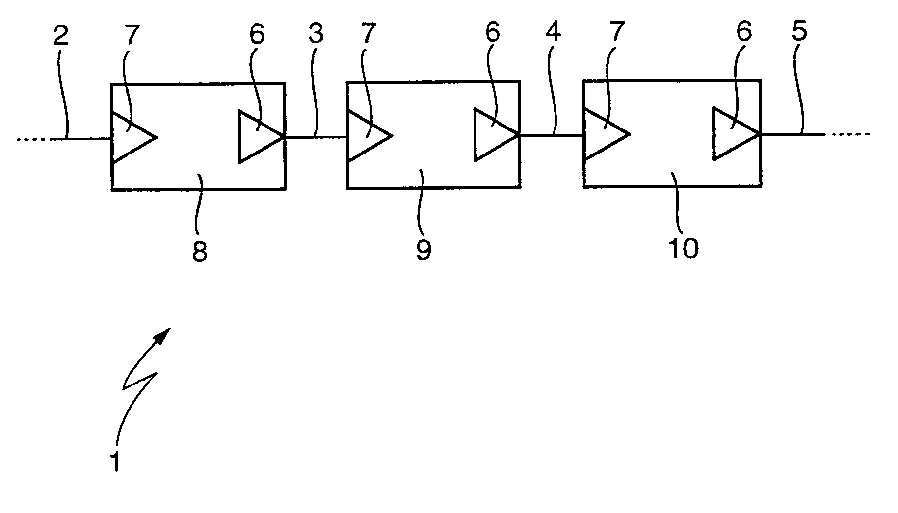
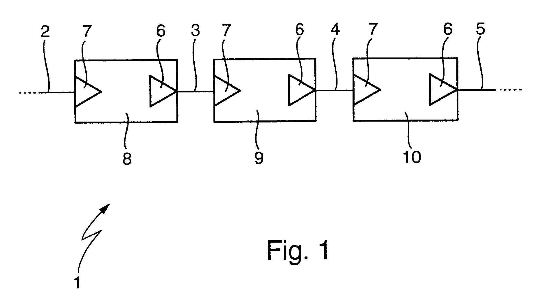
[0029]According to FIG. 1, a data network 1 can exhibit several transmission links 2, 3, 4 and 5, which can be configured as a ring. Each transmission link 2, 3, 4, 5 is defined by a transmitter 6 on the input side and by a receiver 7 on the output side. That is, a transmitter 6 forms the beginning and a receiver 7 forms the end of each transmission link 2, 3, 4, 5. The data network 1 has several network subscribers 8, 9 and 10, which are arranged between successive transmission links 2, 3, 4, 5. Each of these network subscribers 8, 9, 10 includes the receiver 7 of the incoming transmission link 2, 3, 4, 5 and the transmitter 6 of the outgoing transmission link 2, 3, 4, 5. In each network subscriber 8, 9, 10 incoming signals are altered by way of the receiver 7 and forwarded by way of the transmitter 6, whereby the full transmitting power is always available for the next transmission link 2, 3, 4, 5. In particular in an optical data network an optical-electronic-optical change takes...


PUM


Abstract

A method for operating a data network, which includes at least one transmission link, defined by a transmitter and a receiver, wherein in test mode the actual level reserve in the direction of the sensitivity limit, thus between the actual transmitting power of the transmitter and the actual sensitivity limit of the receiver, is determined for at least one transmission link. To better utilize the transmitting capacity of the data network, in test mode, the actual level reserve in the direction of the overload limit, thus between the actual transmitting power of the transmitter and the actual overload limit of the receiver, is also determined for the at least one transmission link.

Description

BACKGROUND AND SUMMARY OF THE INVENTION[0001]This application claims the priority of German Application No. 10055 103.3, filed Nov. 7, 2000, the disclosure of which is expressly incorporated by reference herein.[0002]The invention relates to a method for operating a data network.[0003]U.S. Pat. No. 5,760,940 discloses a method wherein a data network includes a plurality of network subscribers, which are connected to a central unit of the network by means of an input transmission path and an output transmission path. A multiplex unit connects an output line of the central unit to an input line of the respective network subscriber and an input line of the central unit is connected to an output line of the respective network subscriber. Correspondingly this data network is configured in the shape of a star. To determine the actual level reserve of the transmission path between the central unit and one of the network subscribers, the central unit sends a test signal having two different...

Claims


Application Information

Patent Timeline
Patent Type & Authority Patents(United States)
IPC IPC(8): H04L12/26H04L1/24
CPCH04L1/243
Inventor BOESINGER, MARCUSBRANDES, JENSMARQUARDT, DIETERMERGET, PETERPETRY, FRANZ-JOSEFSEIB, HANS-GERDSEIDL, DIETERZEEB, EBERHARD
Owner VOLKSWAGEN AG
Why Eureka
Try Eureka