Eureka AIR delivers breakthrough ideas for toughest innovation challenges, trusted by R&D personnel around the world.

Humidification control method for fuel cell

a fuel cell and control method technology, applied in the direction of fuel cells, solid electrolyte fuel cells, electrical equipment, etc., can solve the problems of complex control method, inability to accurately determine resistance components, and inability to accurately control the trajectory of complex number impedances, etc., to achieve rapid and easy operation and high degree of accuracy reliably

Active Publication Date: 2016-06-14
HONDA MOTOR CO LTD
View PDF18 Cites 0 Cited by
  • Summary
  • Abstract
  • Description
  • Claims
  • Application Information

AI Technical Summary

Benefits of technology

[0015]The present invention has been made to solve problems of this type, and an object of the present invention is to provide a humidification control method for a fuel cell where direct current resistance component can be detected reliably with a high degree of accuracy by measurement of impedance, and humidification control of the fuel cell can be performed rapidly and easily.
[0018]In the present invention, during power generation in the fuel cell, impedance is measured to detect direct current resistance component. Then, since the reaction resistance component is calculated based on the detected direct current resistance component and the stack voltage, it is not required to sweep the alternating current frequency in a wide frequency range from a high frequency to a low frequency. Therefore, the process of measuring impedance can be performed rapidly and easily.
[0019]Accordingly, the direct current resistance component can be detected with a high degree of accuracy reliably by measurement of impedance, and it becomes possible to implement humidification control of the fuel cell rapidly and easily.

Problems solved by technology

Therefore, the control for detection of the resistance components is complicated disadvantageously.
Further, in Cole-Cole Plot where the trajectory of the complex number impedance at each frequency is plotted, the trajectory of the complex number impedance may not form a semicircular shape accurately.
In such a situation, Japanese Laid-Open Patent Publication No. 2003-086220 has a problem where the resistance components cannot be determined correctly.

Method used


Image

  • Humidification control method for fuel cell
  • Humidification control method for fuel cell
  • Humidification control method for fuel cell

Examples


Embodiment Construction

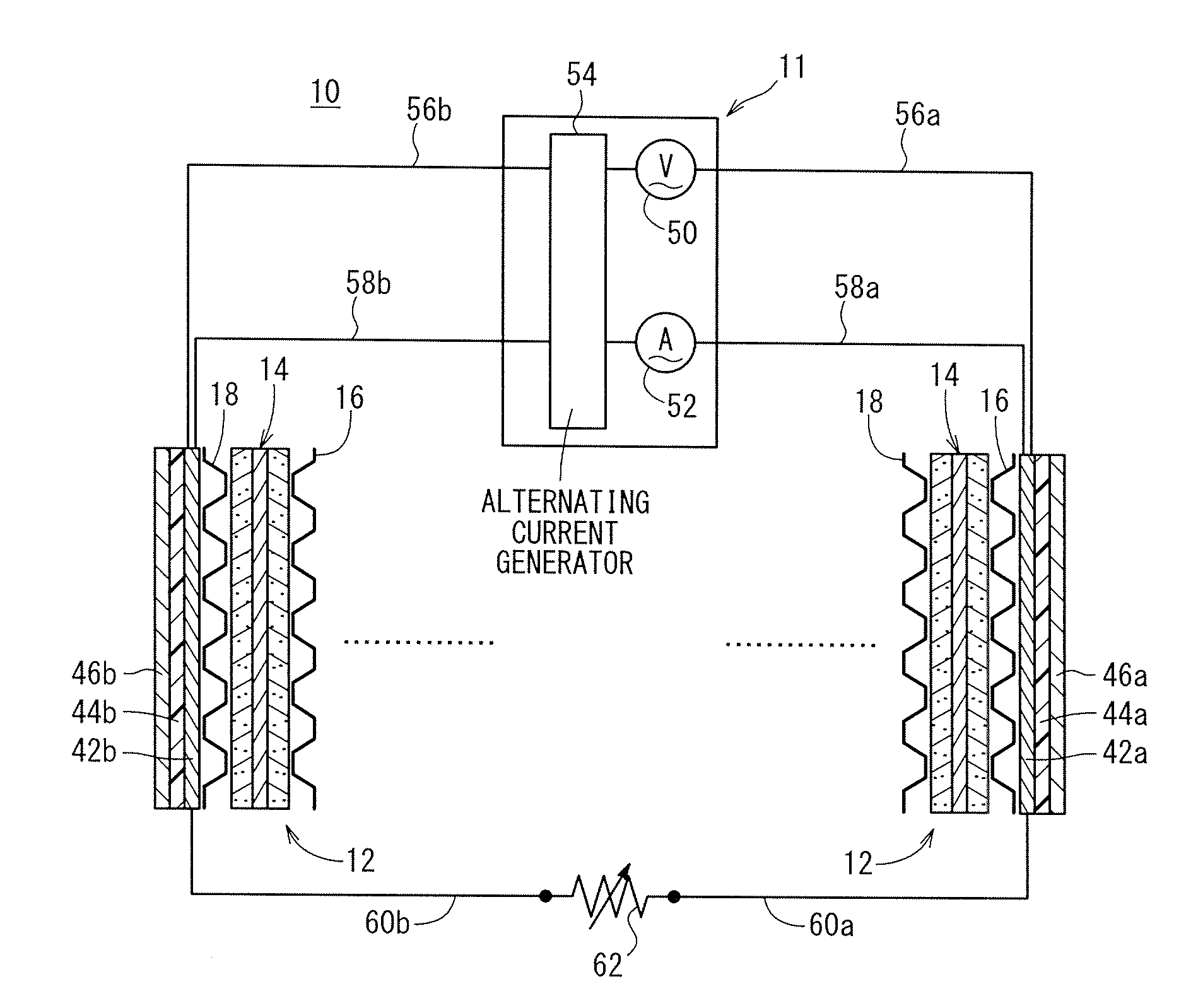
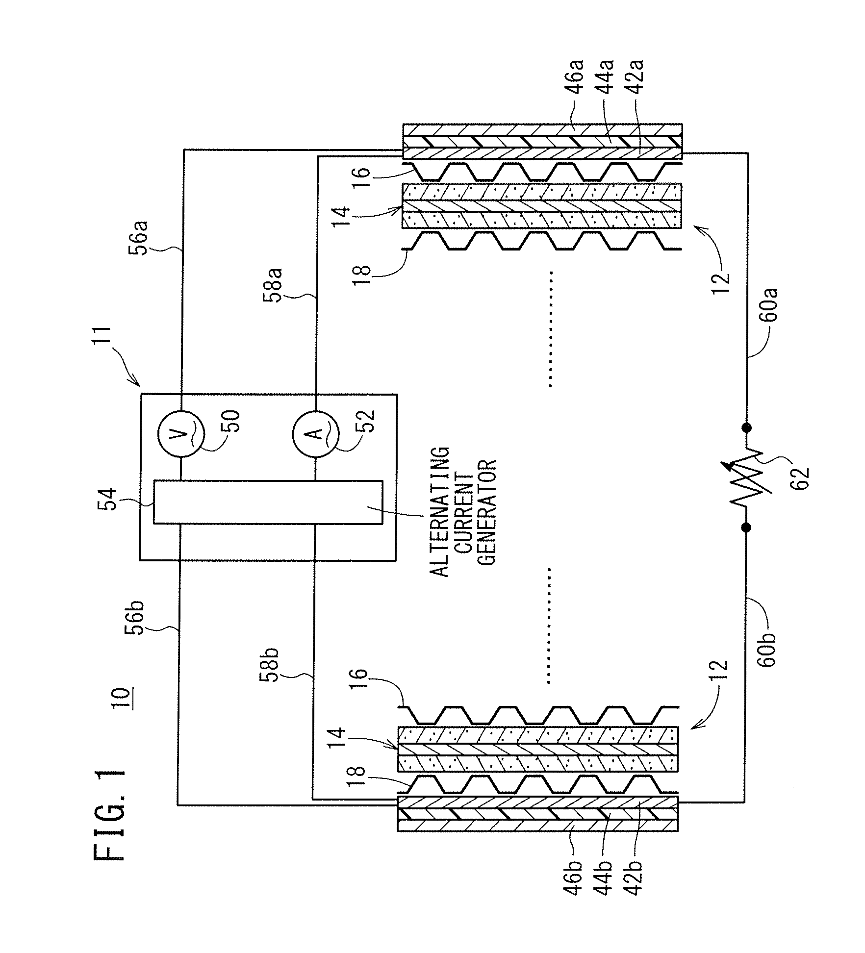
[0031]As shown in FIG. 1, a fuel cell stack 10 to which a humidification control method according to an embodiment of the present invention is applied is formed by stacking a plurality of fuel cells 12, and the fuel cell stack 10 is mounted in a vehicle, for example. Electrical current (alternating current) for impedance measurement flows through at least one of the fuel cells 12, and impedance measurement is performed by an impedance measuring apparatus 11.

[0032]The impedance measurement may be performed in a certain fuel cell 12 in a stacking direction, or may be performed in a plurality of the fuel cells 12 connected electrically in series.

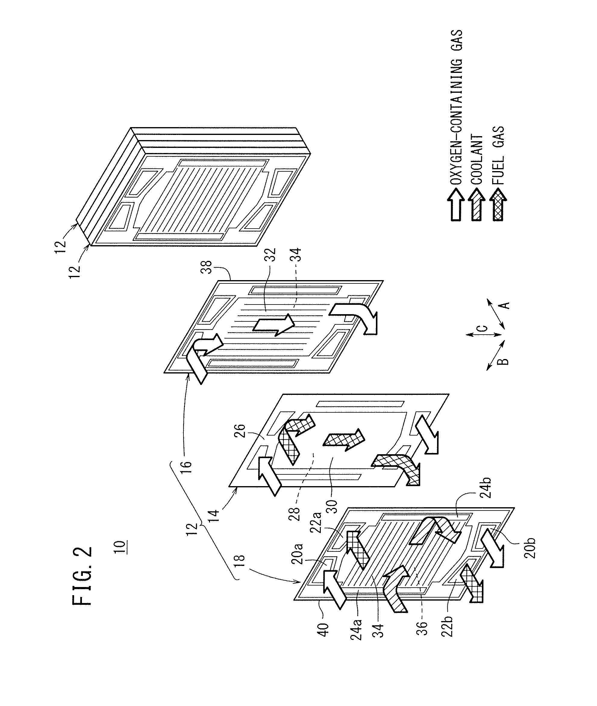
[0033]As shown in FIG. 2, the fuel cell 12 includes a membrane electrode assembly (electrolyte electrode assembly) 14 and a first separator 16 and a second separator 18 sandwiching the membrane electrode assembly 14. At one end (upper end) of the fuel cell 12 in a vertical direction indicated by an arrow C in FIG. 2, an oxygen-containing gas su...


PUM

PropertyMeasurementUnit
frequencyaaaaaaaaaa
frequencyaaaaaaaaaa
alternating current frequencyaaaaaaaaaa

Abstract

A humidification control method includes the steps of detecting a direct current resistance component by measuring impedance during power generation of a fuel cell stack, calculating a reaction resistance component based on the detected direct current resistance component and a stack voltage, detecting a humidified state of the fuel cell stack based on the detected direct current resistance component and the calculated reaction resistance component, and adjusting a quantity of humidification of a reaction gas supplied to the fuel cell stack based on the detected humidified state of the fuel cell stack.

Description

CROSS-REFERENCE TO RELATED APPLICATIONS[0001]This application is based upon and claims the benefit of priority from Japanese Patent Applications No. 2012-268268 filed on Dec. 7, 2012 and No. 2013-232365 filed on Nov. 8, 2013, the contents all of which are incorporated herein by reference.BACKGROUND OF THE INVENTION[0002]1. Field of the Invention[0003]The present invention relates to a humidification control method for a fuel cell formed by stacking an electrolyte electrode assembly and a separator. The electrolyte electrode assembly includes an anode, a cathode, and an electrolyte interposed between the anode and the cathode.[0004]2. Description of the Related Art[0005]For example, a solid polymer electrolyte fuel cell employs a polymer ion exchange membrane as an electrolyte membrane (electrolyte). The polymer electrolyte membrane is interposed between an anode and a cathode to form a membrane electrode assembly (MEA). The membrane electrode assembly and a pair of separators sandwi...

Claims


Application Information

Patent Timeline
Patent Type & Authority Patents(United States)
IPC IPC(8): H01M8/04H01M8/10
CPCH01M8/04835H01M8/04492H01M8/04641Y02E60/50H01M2008/1095
Inventor MOHRI, MASAHIROUEHARA, JUNJIYOSHIDA, HIROMICHIUEDA, KENICHIROWATANABE, SHINYAANDO, AKIJI
Owner HONDA MOTOR CO LTD
Why Eureka
Eureka Blog
Learn More