Universal material testing method and device therefor

a technology of universal material and test method, applied in the field of universal material test method, can solve the problems of the reliability of measurement value and base, and the inability to obtain the true mechanical properties of material, and achieve the effect of easy understanding

Inactive Publication Date: 2006-04-04
NIHON UNIVERSITY
View PDF10 Cites 6 Cited by
  • Summary
  • Abstract
  • Description
  • Claims
  • Application Information

AI Technical Summary

Benefits of technology

[0016]The reference numbers having a parenthesis attached thereto in the claims and the column of means to resolve the problems are conveniently added thereto for more...

Problems solved by technology

Thus, the next load is applied to the test piece before the strain beginning to occur at certain load point stops, which causes the problem of the reliability of the measurement valu...

Method used


Image

  • Universal material testing method and device therefor
  • Universal material testing method and device therefor
  • Universal material testing method and device therefor

Examples


Embodiment Construction

[0021]A concrete form of embodiment of the invention will be described and illustrated with reference to the drawings hereinafter.

[0022]The test apparatus of the invention can be used as universal material test machine such as a tension test machine, a compression test machine, a bending test machine, etc, but in the present embodiment, it will be explained as the tensile test machine.

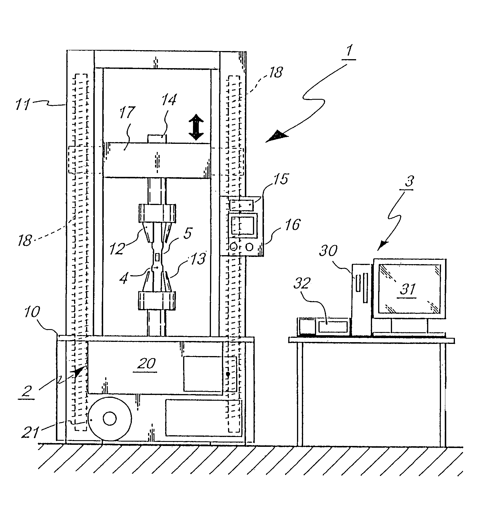
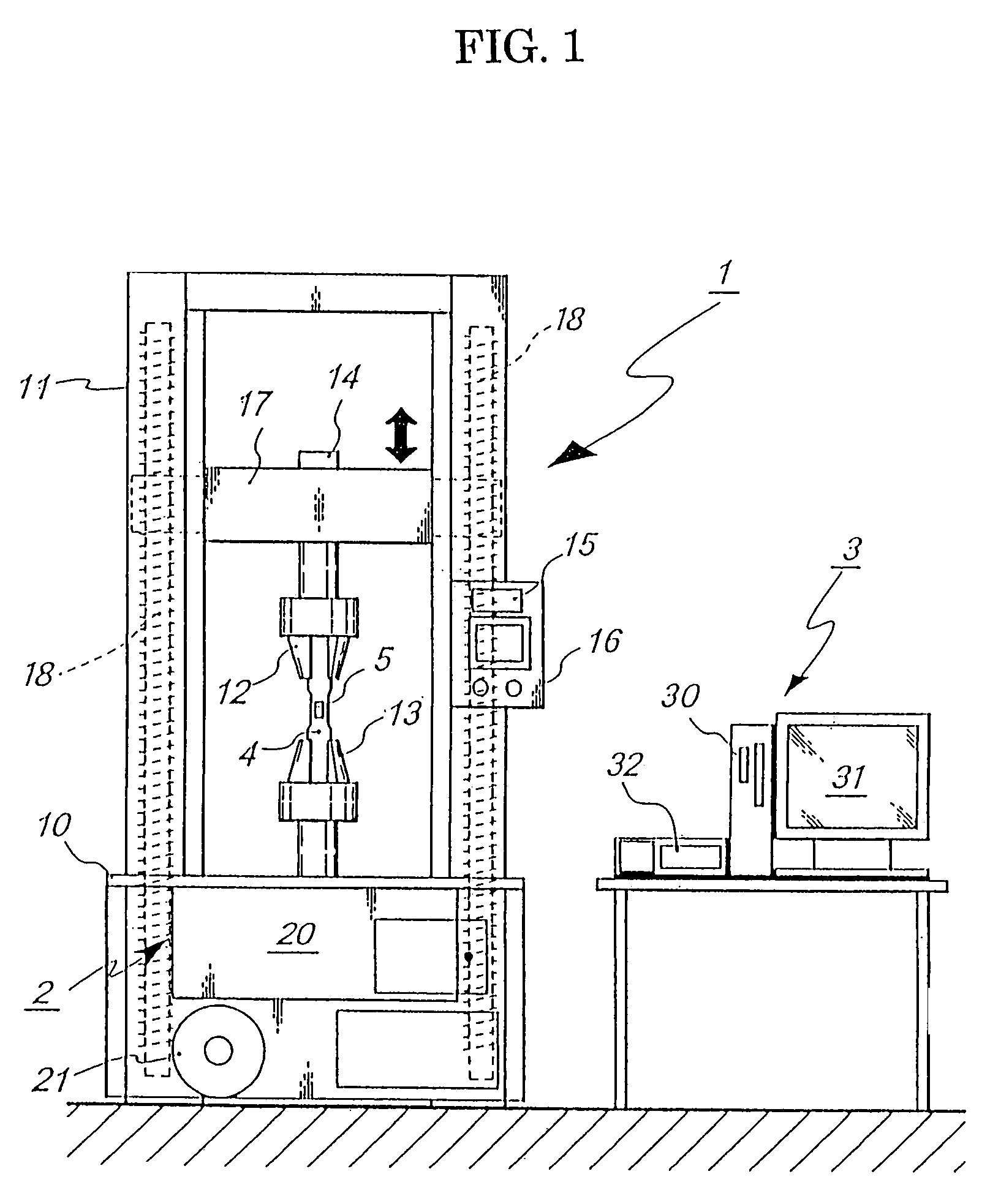
[0023]The tensile test machine 1 according to the present embodiment may have the construction similar to that of the test machine described with reference to the prior test method and comprises a base 10, a support frame 11, upper and lower chucks 12 and 13, a load cell 14, a crosshead 17, ball screws 18 and a loading mechanism 2.

[0024]Onto the support frame 11 are disposed and attached an indicator to indicate initial setting information for arranging the mount of the test piece 4 on the upper and lower chucks 12 and 13 and an operation box 16 to perform the operation thereof. The load mechanism 2 co...


PUM


Abstract

A load increasing in a stepped manner from an initial load is applied to a test piece (4) of material in order to examine mechanical properties of the material by applied load, but the load having a next step load added thereto is applied to the test piece after it is confirmed that the variation of strain within a unit time applied to the test piece in the load (Wn) applied in each step falls within a predetermined value whereby there are measured physical variation and time variation in the load applied in each step. The load applied to the test piece is preferably kept at a constant value and the applied load (Wn) and and time variation are preferably recorded.

Description

TECHNICAL FIELD[0001]This invention relates to a universal material test method used for evaluating physical properties of an objective material by loading tension, compression, bending etc. to a test piece of the objective material and an apparatus for carrying out the test method.BACKGROUND OF THE INVENTION[0002]Describing a tension tester as an example of a test machine used for the universal material test, this tension tester 1 is shown in FIG. 1 and comprises a base 10, a gate-shaped support frame 11 disposed on an upper face of the base 10 and opened on its front and rear sides, upper and lower chucks 12 and 13 provided at upper and lower positions of the base 10, respectively to grapes the test piece 4 and a load mechanism 2 for tension load provided on one of the chucks, which is the upper chuck 12 in the illustrated example through a load cell 14, for example. The other chuck, which is the lower chuck 13 in the illustrated example, is securely attached to the base 10.[0003]...

Claims


Application Information

Patent Timeline
IPC IPC(8): G01N3/00G01N3/02G01N3/08G01N3/20
CPCG01N3/08G01N2203/0208G01N2203/0075
Inventor IMAMURA, SENJI
Owner NIHON UNIVERSITY
Why Eureka
Try Eureka