Internal EGR parameter estimating device for internal combustion engine

a technology of internal combustion engine and internal combustion engine, which is applied in the direction of machines/engines, output power, electric control, etc., can solve the problems of insufficient accuracy of calculated difficult to reflect the effect of the change in the calculation effective cross sectional area opening, and inability to adapt easily. to achieve the effect of improving the accuracy of calculation

Active Publication Date: 2006-04-04
NISSAN MOTOR CO LTD
View PDF3 Cites 19 Cited by
  • Summary
  • Abstract
  • Description
  • Claims
  • Application Information

AI Technical Summary

Benefits of technology

[0011]One object of the present invention is to calculate the effective cross sectional area opening accurately, and thereby, calculate the blow-by gas quantity accurately when estimating the internal EGR quantity. In other words, an object of the present invention is to calculate the blow-by gas quantity during the overlap period in a simple and accurate manner, and thereby, estimate the internal EGR quantity accurately.

Problems solved by technology

It has been discovered that in the device described above, in which an overlap compensation valve is added to a basic value, has some problems.
Furthermore, even if one is successful in adapting, re-adaptation is not easily accomplished when the profiles of the cams and / or the shapes of the ports have changed.
However the following problem was discovered regarding the calculation of the effective cross sectional area opening in such a device.
Since the relationship between the amount of overlap and the integrated cross sectional area is identified in advance and stored as a map, if the valve clearance changes (the clearances of the intake valve and the exhaust valve are also sometimes different) and causes the effective instantaneous cross sectional area openings to change, it is difficult to reflect the effect of the change in the calculated effective cross sectional area opening.
Consequently, the accuracy of the calculated effective cross sectional area opening is insufficient and the blow-by gas quantity cannot be calculated accurately.

Method used


Image

  • Internal EGR parameter estimating device for internal combustion engine
  • Internal EGR parameter estimating device for internal combustion engine
  • Internal EGR parameter estimating device for internal combustion engine

Examples


Embodiment Construction

[0031]Selected embodiments of the present invention will now be explained with reference to the drawings. It will be apparent to those skilled in the art from this disclosure that the following descriptions of the embodiments of the present invention are provided for illustration only and not for the purpose of limiting the invention as defined by the appended claims and their equivalents.

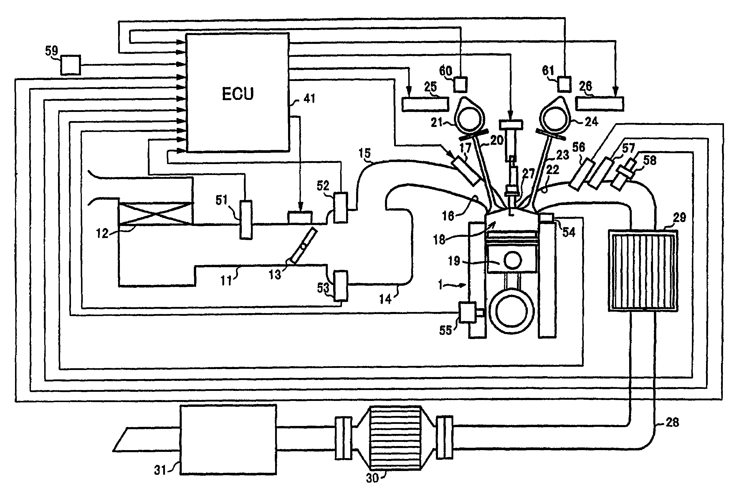
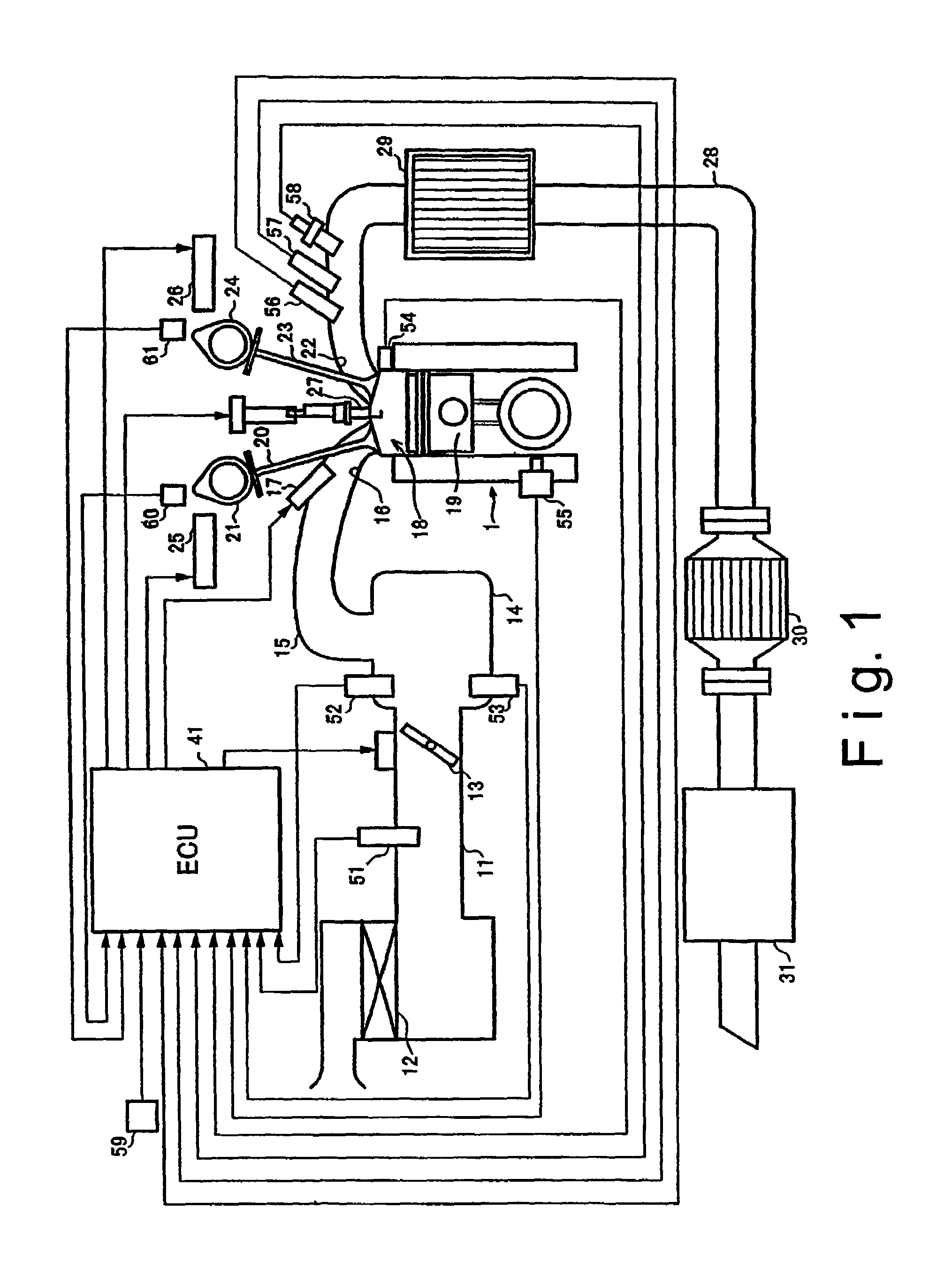
[0032]Referring initially to FIG. 1, the main features of an internal combustion engine 1 is illustrated that is provided with an internal EGR parameter estimating device in accordance with a preferred embodiment of the present invention. The internal EGR parameter estimating device of the present invention offers a blow-by gas quantity calculating device or section and an internal EGR quantity estimating device or section for the engine 1. As explained below, the blow-by gas calculating device in accordance with the present invention calculates the quantity of blow-by gas of the engine 1, i.e., th...


PUM


Abstract

An internal EGR parameter estimating device is configured to estimate the internal EGR quantity based on the quantity of blow-by gas that blows by during an overlap period when both the intake valve(s) and the exhaust valve(s) are open. The blow-by gas quantity is calculated based on the intake air pressure and the exhaust gas pressure during the overlap period and the effective cross sectional area opening formed by the intake and exhaust valves. The overlap period is divided into intervals of a prescribed period and the interval cross sectional area opening during each interval is calculated.

Description

CROSS-REFERENCE TO RELATED APPLICATIONS[0001]This application claims priority to Japanese Patent Application Nos. 2004-124025 and 2004-124032. The entire disclosures of Japanese Patent Application Nos. 2004-124025 and 2004-124032 are hereby incorporated herein by reference.BACKGROUND OF THE INVENTION[0002]1. Field of the Invention[0003]The present invention generally relates to an internal EGR parameter estimating device for an internal combustion engine. More specifically, the present invention relates to a technology for calculating the quantity of exhaust gas that blows between the exhaust side and the intake side during the overlap period when both the intake valve and the exhaust valve are open (i.e., the blow-by gas quantity) in a simple and accurate fashion.[0004]2. Background Information[0005]Conventionally, engines are configured to execute exhaust gas recirculation (hereinafter called “EGR”) whereby a portion of the exhaust gas is returned to the cylinders in order to supp...

Claims


Application Information

Patent Timeline
Patent Type & Authority Patents(United States)
IPC IPC(8): F02B47/08F02D13/02F02D21/08F02D41/00F02M25/07
CPCF02D13/0261F02M25/0752F02D41/0062F02D13/0219Y02T10/18Y02T10/47F02M26/01Y02T10/12Y02T10/40E04G7/06E04G21/242E04G21/246E04G21/28
Inventor NAKAZAWA, TAKASHIKOSEKI, TAKAHISANAGAISHI, HATSUOSUZUKI, TAKESHI
Owner NISSAN MOTOR CO LTD
Why Eureka
Try Eureka