Transmission controller and vehicle including the same

a technology of transmission controller and transmission shaft, which is applied in the direction of machines/engines, interengaging clutches, instruments, etc., can solve the problems of inability to detect abnormal conditions through the senses of the operator, inability to accurately adjust the shift shaft, and inability to achieve accurate shift changes. achieve the effect of more accurate shift changes

Active Publication Date: 2008-05-01
YAMAHA MOTOR CO LTD
View PDF1 Cites 23 Cited by
  • Summary
  • Abstract
  • Description
  • Claims
  • Application Information

AI Technical Summary

Benefits of technology

[0011]Thus, an actuator-based system is desired in which a transmission controller is provided to provide more accurate shift changes.

Problems solved by technology

However, the following problems arise from the method for correcting the neutral position shown in JP-A-2000-27991.
In the process of manufacturing a number of vehicles, mechanical rotation limits of the shift shaft in its forward rotation and reverse rotation are different for each vehicle due to design limitations, tolerance stacking or assembly of components, among other reasons.
In this case, when the improperly calculated neutral position is established as a reference, accurate shift change is not likely to be attained.
However, when an actuator is used to cause a shift change, such an abnormal condition cannot be detected through the senses of the operator.

Method used


Image

  • Transmission controller and vehicle including the same
  • Transmission controller and vehicle including the same
  • Transmission controller and vehicle including the same

Examples


Embodiment Construction

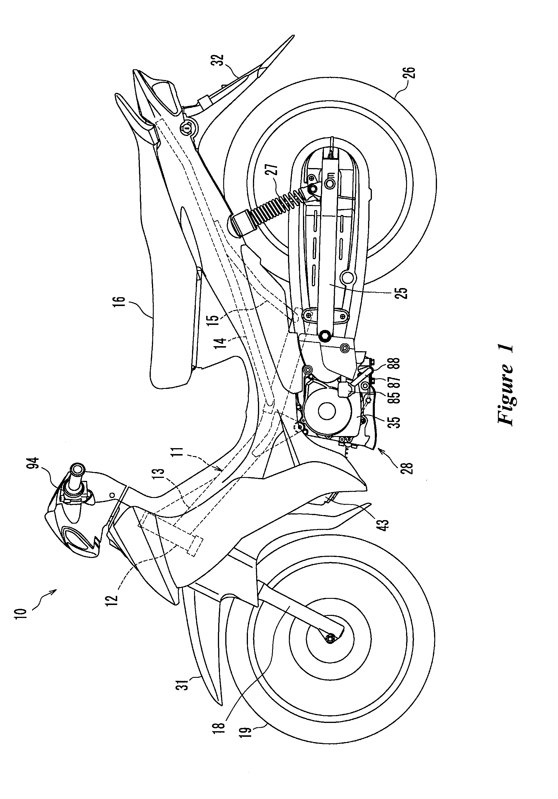
[0034]With reference initially to FIG. 1, the illustrated straddle type vehicle is a motorcycle 10. Other straddle type vehicles also can benefit from certain features, aspects and advantages of the present invention. As used herein, a straddle type vehicle generally refers to a vehicle in which the legs of a rider are position to lateral sides of a seat or other seating area. The motorcycle 10 can be a so-called moped-type or scooter-type of motorcycle. However, these are but two examples of the type of vehicles that can benefit from certain features, aspect and advantages of the present invention. Thus, by illustrating a moped-type or scooter-type of motorcycle, the maximum speed, displacement amount or the like of the vehicle is not meant to be restrict nor is the size or the like of the vehicle meant to be restricted. Thus, the motorcycle can be of the type having a fuel tank placed in front of a seat and the straddle type vehicle can be a type of vehicle other than the illustra...


PUM


Abstract

A transmission controller includes a rotatable shaft that controls engagement and disengagement of a variable speed clutch. An actuator, such as an electric motor, drives the shaft. The shaft is rotated alternately in the normal and reverse directions by supplying a low level current to such an extent that a clutch transfer mechanism is not operated by the rotation. Rotation stop positions are detected. A play area between the rotation stop positions is calculated and can be used to correct for manufacturing inaccuracies or for wear occurring over time.

Description

CROSS-REFERENCE TO RELATED APPLICATIONS[0001]This application claims the benefit of Japanese Patent Application No. JP 2006-292897, filed on Oct. 27, 2006, the disclosure of which is incorporated herein by reference in its entirety.BACKGROUND OF THE INVENTION[0002]1. Field of the Invention[0003]The present invention generally relates to a transmission controller that drives an actuator, such as a motor, to cause engagement and disengagement of a clutch and to cause a speed change of a transmission. The present invention also generally relates to a vehicle including such a transmission controller.[0004]2. Description of the Related Art[0005]A transmission controller can be used to control a motor that drives a shift shaft. Rotation of the shift shaft can be used to control engagement and disengagement of a clutch and to control change of gear ratios with varied gear combinations. See JP-A-2000-27991. This type of transmission controller has a clutch transfer mechanism located between...

Claims


Application Information

Patent Timeline
Patent Type & Authority Applications(United States)
IPC IPC(8): G06F17/00B62D61/02B60W10/04B60W10/06B60W10/10B60W10/11F02D29/00F16D23/12F16D28/00F16H59/42F16H59/68F16H61/16F16H61/68F16H61/682F16H63/50
CPCF16D11/10F16D28/00F16D48/068F16D2011/008F16D2500/1025Y10T74/19251F16D2500/308F16D2500/50251F16D2500/70412F16D2500/70464F16D2500/3022
Inventor HIROI, KAZUTAKA
Owner YAMAHA MOTOR CO LTD
Why Eureka
Try Eureka