Exhaust gas cleaning system for internal combustion engine

a technology for cleaning systems and internal combustion engines, which is applied in the direction of exhaust treatment electric control, electrical control, separation process, etc., can solve the problems of catalyst degraded, dpf may be excessively heated with combustion heat of particulate matter, and the emission of particulate matter included in the exhaust gas of a diesel engin

Active Publication Date: 2004-07-01
DENSO CORP
View PDF8 Cites 32 Cited by
  • Summary
  • Abstract
  • Description
  • Claims
  • Application Information

AI Technical Summary

Problems solved by technology

Emission of particulate matters included in exhaust gas of a diesel engine is a problem to be solved.
However, under some conditions, there is a possibility that the DPF may be heated excessively with combustion heat of the particulate matters.
As a result, the catalyst may be degraded or a filter base material may be damaged.
However, as a matter of fact, it is difficult to directly sense the temperature at the center of the device.
As a result, the temperature of the catalyst cannot be maintained in a proper range.
In addition, estimated temperature may deviate from actual temperature largely because of catalytic reaction or combustion of the particulate matters.
In that case, there is a possibility that the catalyst may be degraded.
In the determination of the degradation of the catalyst disclosed in the second patent document, it is difficult to determine whether a difference between outputs of the two temperature sensing means is a temperature change caused by the catalytic reaction or a change in the temperature of the exhaust gas itself (a change in the temperature of the exhaust gas before entering the exhaust gas after-treatment device).
However, in the actual travel, the vehicle travels at a constant speed infrequently.
Therefore, there is a practical problem in the above method.

Method used


Image

  • Exhaust gas cleaning system for internal combustion engine
  • Exhaust gas cleaning system for internal combustion engine
  • Exhaust gas cleaning system for internal combustion engine

Examples


first embodiment

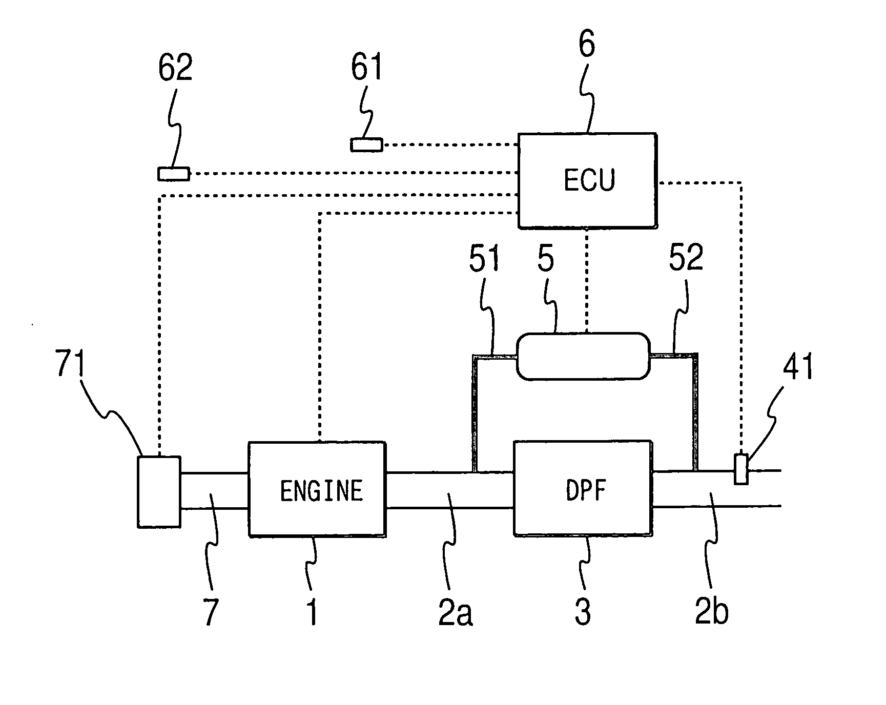
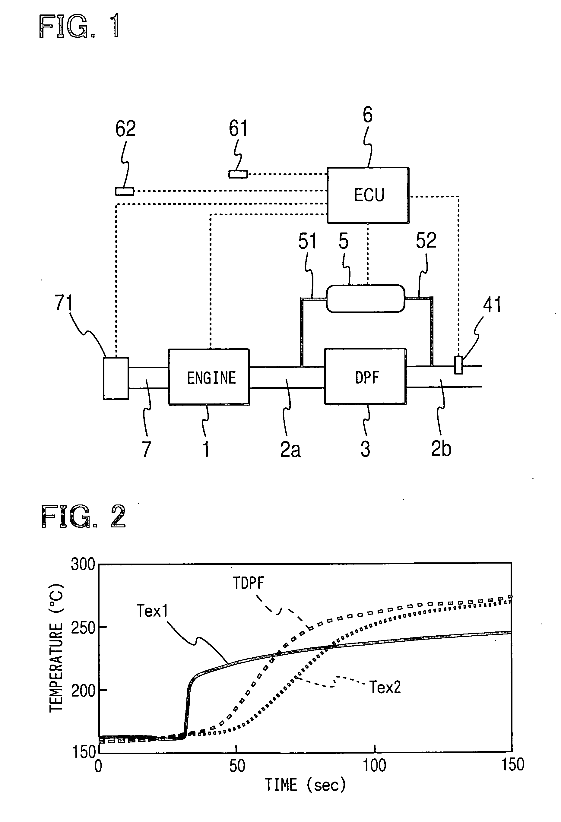
[0032] Referring to FIG. 1, an exhaust gas cleaning system for a diesel engine 1 according to the first embodiment of the present invention is illustrated. In an exhaust passage of the engine 1, a diesel particulate filter (DPF) 3 having an oxidation catalyst as an exhaust gas after-treatment device is disposed between an upstream exhaust pipe 2a and a downstream exhaust pipe 2b. The DPF 3 is formed of heat-resistant ceramics such as cordierite in the shape of a honeycomb having a multiplicity of cells as exhaust gas passages, which are provided by filter walls. An inlet or an outlet of each cell is blocked alternately. The oxidation catalyst such as platinum is applied to surfaces of the filter walls of the cells. The exhaust gas discharged from the engine 1 flows downstream while passing through the porous filter wall of the DPF 3. Thus, particulate matters included in the exhaust gas are collected and accumulated in the DPF 3 gradually.

[0033] An exhaust gas temperature sensor 41 ...

second embodiment

[0055] Next, an exhaust gas cleaning system according to the second embodiment will be explained based on FIG. 7. As shown in FIG. 7, an exhaust gas temperature sensor 42 as inlet gas temperature sensing means is disposed in the exhaust pipe 2a upstream of the DPF 3 having the, oxidation catalyst. The exhaust gas temperature sensor 42 senses the inlet gas temperature of the DPF 3 and outputs a signal corresponding to the inlet gas temperature to the ECU 6. The exhaust gas cleaning system of the second embodiment determines the degradation of the oxidation catalyst based on estimated values of the DPF central temperature calculated from the outlet gas temperature and the inlet gas temperature.

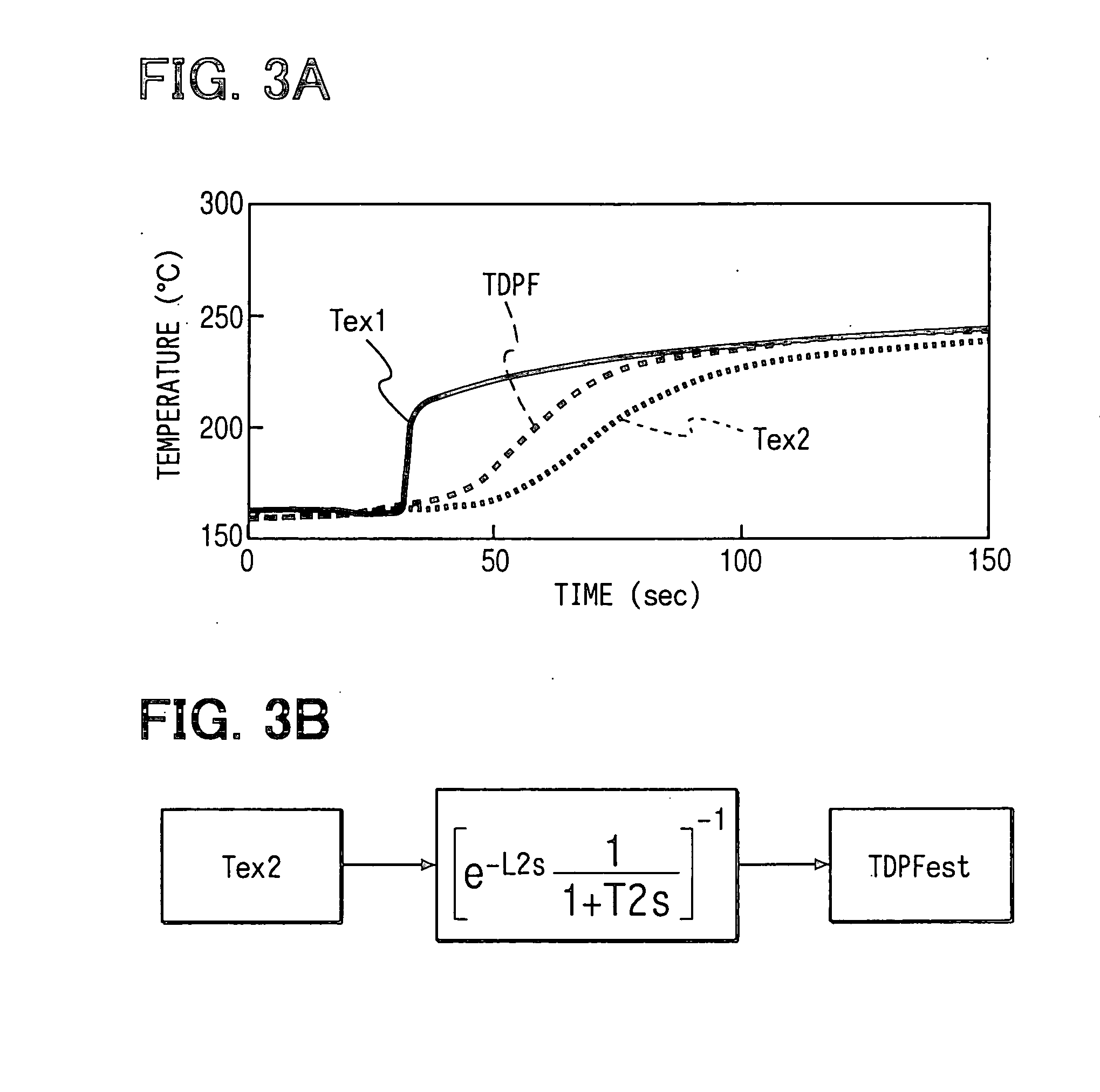
[0056] The ECU 6 of the second embodiment has second temperature estimating means for calculating the estimated central temperature of the DPF 3, which reflects the effect of the heat generation caused by the catalytic reaction, based on the output values of the exhaust gas temperature sensor 41...


PUM


Abstract

A diesel particulate filter (DPF) having an oxidation catalyst is disposed between exhaust pipes of an internal combustion engine. An exhaust gas temperature sensor senses outlet gas temperature of the DPF. An engine control unit (ECU) calculates estimated central temperature of the DPF from an output of the exhaust gas temperature sensor with the use of an inverse transfer function of a change in the outlet gas temperature with respect to a change in temperature of the DPF. Based on the estimated temperature, the ECU performs excessive temperature increase prevention control or regeneration control of the DPF. The transfer function is simply expressed with first-order lag and dead time. A time constant of the first-order lag and the dead time are set in accordance with an exhaust gas flow rate.

Description

[0001] This application is based on and incorporates herein by reference Japanese Patent Application No. 2002-291503 filed on Oct. 3, 2002.[0002] 1. Field of the Invention[0003] The present invention relates to an exhaust gas cleaning system for an internal combustion engine having an exhaust gas after-treatment device. Specifically, the present invention relates to the exhaust gas cleaning system for the internal combustion engine capable of estimating temperature of the exhaust gas after-treatment device and maintaining the exhaust gas after-treatment device in an optimum state, based on the estimated temperature.[0004] 2. Description of Related Art[0005] Conventionally, as means for protecting the environment, various exhaust gas after-treatment devices for reducing air pollutants discharged from an internal combustion engine are proposed. For instance, catalyst systems such as an oxidation catalyst, a NOx removal catalyst and a three-way catalyst have been introduced progressive...

Claims


Application Information

Patent Timeline
Patent Type & Authority Applications(United States)
IPC IPC(8): B01D53/94F01N3/02F02D45/00F01N3/18F01N3/20F01N3/24F01N11/00
CPCF01N11/002Y02T10/22Y02T10/47F01N11/005Y02T10/12Y02T10/40
Inventor KUBOSHIMA, TSUKASAOKUGAWA, SHINICHIROKINUGAWA, MASUMISEKIGUCHI, KIYONORI
Owner DENSO CORP
Why Eureka
Try Eureka