Semiconductor device, magnetic sensor, and physical quantity sensor

a magnetic sensor and semiconductor technology, applied in the direction of galvano-magnetic hall-effect devices, instruments, material magnetic variables, etc., can solve the problems of complex correction, unbalanced resistance value within the hall element, and mechanical stress not uniformly applied to the hall element, and achieve excellent linearity and high accuracy

Inactive Publication Date: 2008-03-27
DENSO CORP
View PDF8 Cites 34 Cited by
  • Summary
  • Abstract
  • Description
  • Claims
  • Application Information

AI Technical Summary

Benefits of technology

[0031] An arithmetic calculation for canceling the temperature characteristic can be made between the Hall voltage and the temperature monitor voltage. The above sensor output obtained through such an arithmetic calculation also becomes a voltage having a characteristic naturally excellent in linearity with respect to the temperature change. Therefore, when an interpolation correction, etc. based on temperature with respect to the above sensor output are made, its accuracy is suitably maintained. Accordingly, the change of the Hall voltage caused by the temperature characteristic can be corrected on the basis of high accuracy.
[0033] In accordance with the above construction, an arithmetic calculation for canceling the temperature characteristics of the switched and outputted Hall voltage and temperature monitor voltage is made by these voltages. The above sensor output obtained through such an arithmetic calculation also becomes a voltage having a characteristic naturally excellent in linearity with respect to the temperature change. Therefore, when an interpolation correction, etc. based on temperature with respect to the above sensor output are made, its accuracy is suitably maintained, and the change of the Hall voltage caused by the temperature characteristic can be corrected on the basis of high accuracy.

Problems solved by technology

Such mechanical stress is not uniformly applied to the Hall element.
Therefore, an unbalance is generated with respect to the resistance value within the Hall element.
On the other hand, with respect to the above change caused by temperature characteristic, the correction every each temperature is required so that its correction is complicated and cannot be also neglected from a viewpoint of improvement of detection accuracy of the Hall element
Further, if the curve correction is made, a circuit scale is increased and an increase of a chip size is caused.
Therefore, in each case, non-efficiency is caused.
Therefore, a bending degree of a curve showing the relation of temperature and the Hall voltage in the above temperature characteristic tends to be more emphasized, and the correction of the Hall voltage caused by the temperature characteristic is more complicated.
Therefore, dispersion of the Hall voltage every individual also becomes large.
It becomes difficult to precisely correct the change of the Hall voltage caused by the temperature characteristic.

Method used


Image

  • Semiconductor device, magnetic sensor, and physical quantity sensor
  • Semiconductor device, magnetic sensor, and physical quantity sensor
  • Semiconductor device, magnetic sensor, and physical quantity sensor

Examples


first embodiment

Mode

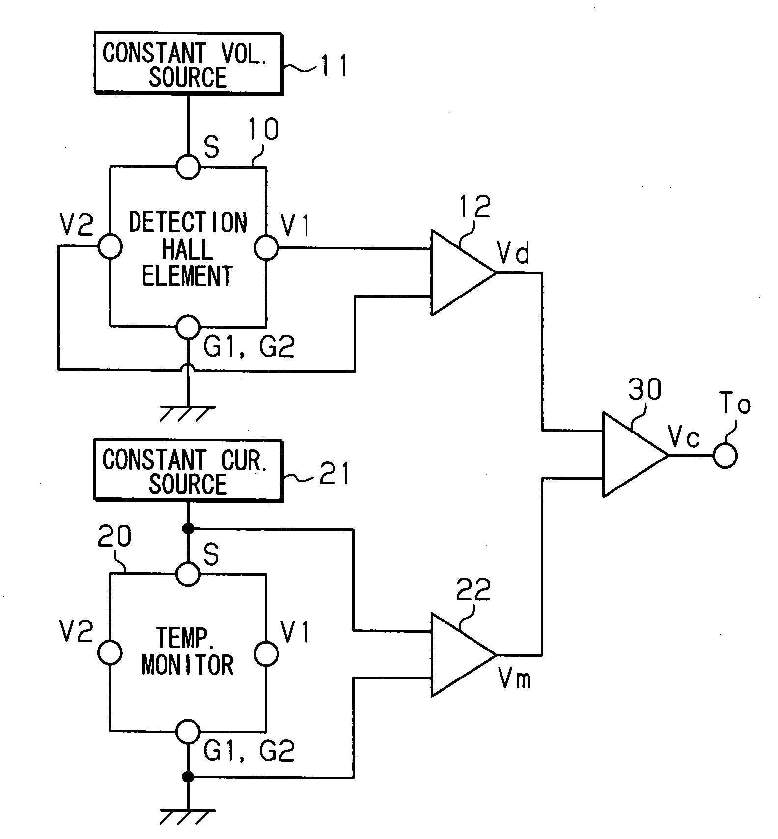
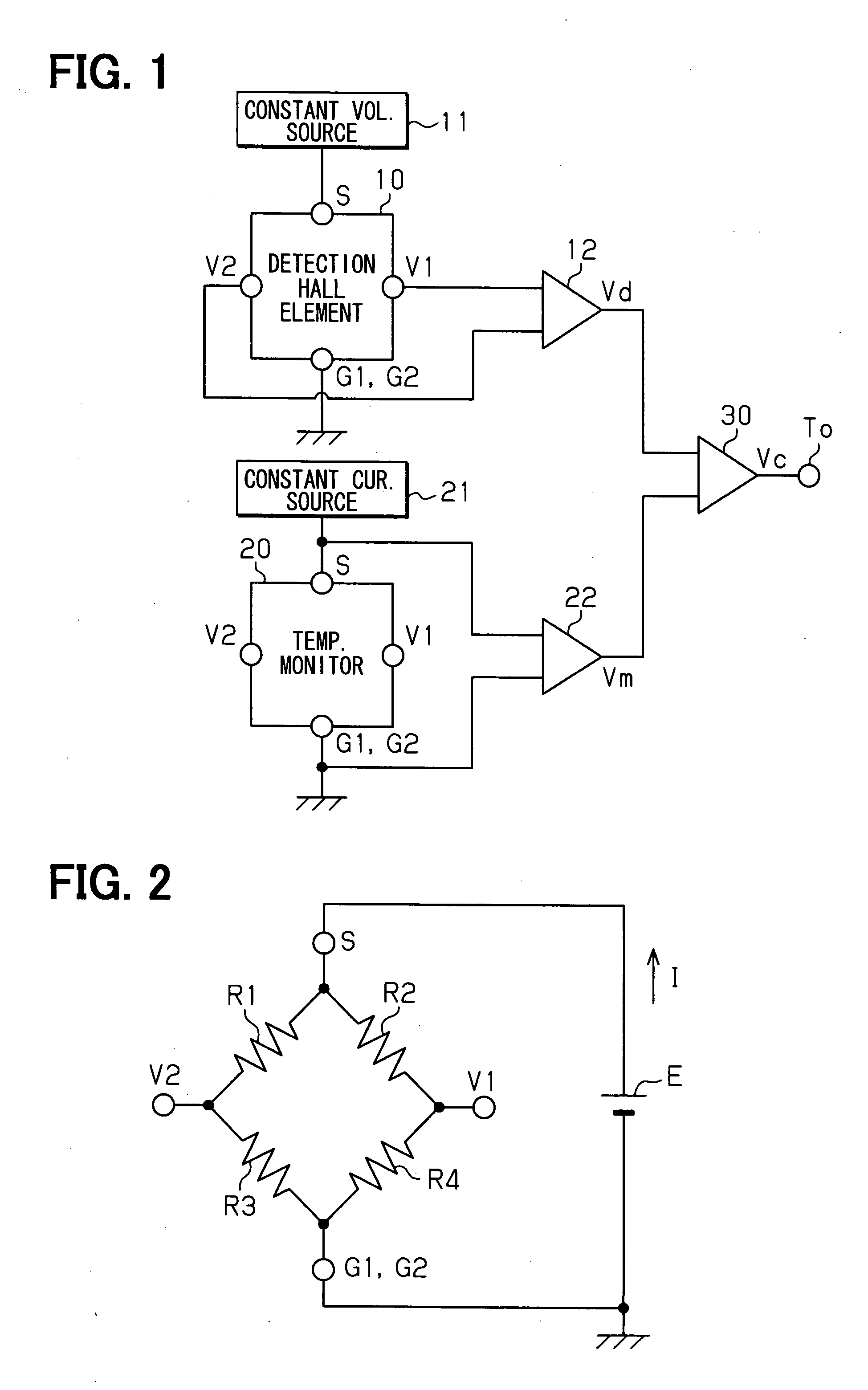
[0065] A first embodiment mode for embodying a magnetic sensor will next be explained with reference to FIGS. 1 to 5. In the magnetic sensor in accordance with this embodiment mode, the above vertical Hall element is adopted as an element for detecting magnetism.

[0066] As shown in FIG. 1, the magnetic sensor in accordance with this embodiment mode is constructed by arranging a vertical Hall element (detection vertical Hall element) 10 for detecting a magnetic field emitted from a detection object, and a temperature monitor vertical Hall element (vertical Hall element for monitoring temperature) 20 having the same characteristics as this detection vertical Hall element 10. These detection vertical Hall element 10 and temperature monitor vertical Hall element 20 are formed in close positions of the same substrate. The arrangements of these detection vertical Hall element 10 and temperature monitor vertical Hall element 20 are arbitrary. However, when the width of a magnetic field...

second embodiment

Mode

[0086] Next, a second embodiment mode for embodying the magnetic sensor in the present invention will be explained. The magnetic sensor in accordance with this embodiment mode also has a construction similar to that of the magnetic sensor in accordance with the previous first embodiment mode.

[0087] As shown in FIG. 6, in the magnetic sensor in accordance with this embodiment mode, the terminal S of the detection vertical Hall element 10 is connected to the constant electric current driving source 21, and terminals G1, G2 are connected to the terminal S of the temperature monitor vertical Hall element 20. Both the terminals G1, G2 of the temperature monitor vertical Hall element 20 are connected to the ground. Thus, in the magnetic sensor in accordance with this embodiment mode, the previous detection vertical Hall element 10 and the previous temperature monitor vertical Hall element 20 are connected in series to the constant electric current driving source 21. Both the detectio...

third embodiment

Mode

[0094] A third embodiment mode for embodying the magnetic sensor in the present invention will next be explained. In the magnetic sensor in accordance with this embodiment mode, a function born in each of the previous detection vertical Hall element and the previous temperature monitor vertical Hall element is realized by a single Hall element. Such a magnetic sensor will be explained with reference to FIG. 8. FIG. 8 typically shows a circuit construction of the magnetic sensor in accordance with this embodiment mode.

[0095] As shown in FIG. 8, terminal S of a vertical Hall element 50 is connected to a constant electric current driving source 51, and terminals G1, G2 are connected to the ground. Further, these terminals S, G1, G2 and terminals V1, V2 of the vertical Hall element 50 are respectively connected to a switch circuit 52. Two input terminals of an adder circuit 53 are connected to this switch circuit 52.

[0096] This switch circuit 52 is constructed by arranging four fi...


PUM


Abstract

A semiconductor device includes: a detection Hall element for detecting a magnetic field; a temperature monitor Hall element; and a calculation circuit. The detection Hall element has a characteristic, which is almost a same as the temperature monitor Hall element. The detection Hall element is disposed near the temperature monitor Hall element. The detection Hall element outputs a Hall voltage. The temperature monitor Hall element includes a pair of driving signal supply terminals for outputting a temperature monitor voltage. The calculation circuit calculates to cancel a temperature characteristic of the Hall voltage based on the Hall voltage and the temperature monitor voltage.

Description

CROSS REFERENCE TO RELATED APPLICATIONS [0001] This application is based on Japanese Patent Applications No. 2006-154803 filed on Jun. 2, 2006, and No. 2007-81376 filed on Mar. 27, 2007, the disclosures of which are incorporated herein by reference. FIELD OF THE INVENTION [0002] The present invention relates to a semiconductor device, a magnetic sensor, and a physical quantity sensor. BACKGROUND OF THE INVENTION [0003] A magnetic sensor for detecting a physical quantity can detect motion such as movement, rotation, etc. of a detection object constructed by a magnetic substance in non-contact. Accordingly, for example, the magnetic sensor is used in a throttle valve aperture sensor, etc. of a vehicle mounting internal combustion engine as an angle detecting sensor. In particular, the magnetic sensor constructed by arranging a Hall element as an element for utilizing the Hall effect can also distinguish a magnetic pole. Therefore, this magnetic sensor is also widely utilized in a magn...

Claims


Application Information

Patent Timeline
Patent Type & Authority Applications(United States)
IPC IPC(8): G01B7/24G01R33/07
CPCG01R33/077G01R33/07
Inventor OOHIRA, SATOSHI
Owner DENSO CORP
Why Eureka
Try Eureka