
Method to implement full six-degree target shift corrections in radiotherapy

a target shift and correction technology, applied in the field of correcting errors, can solve the problems of other methods such as fixed points, and achieve the effect of facilitating correction and facilitating target position variations

Inactive Publication Date: 2007-02-01
UPMC
View PDF9 Cites 32 Cited by
  • Summary
  • Abstract
  • Description
  • Claims
  • Application Information

AI Technical Summary

Benefits of technology

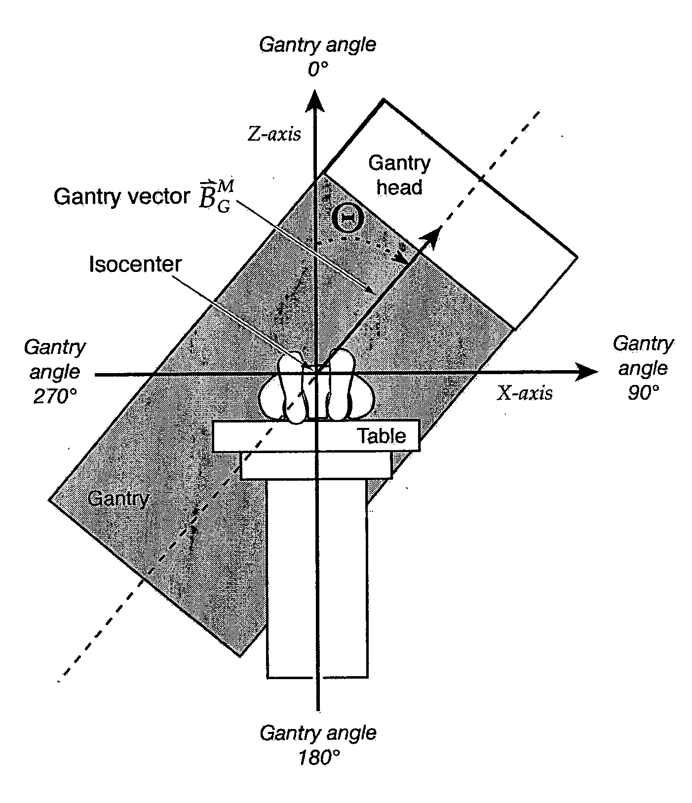
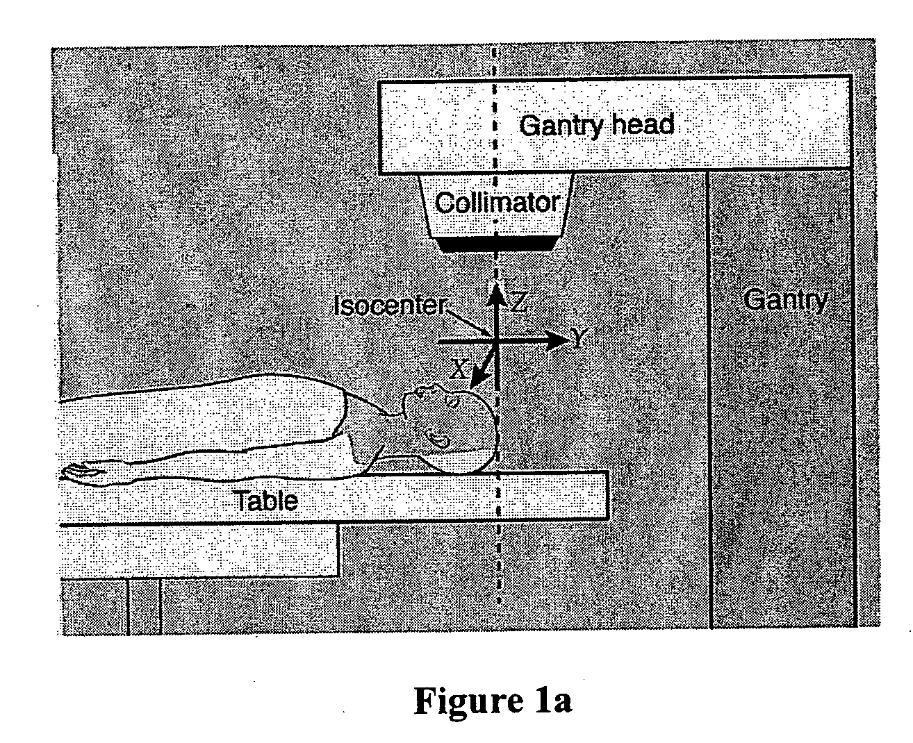
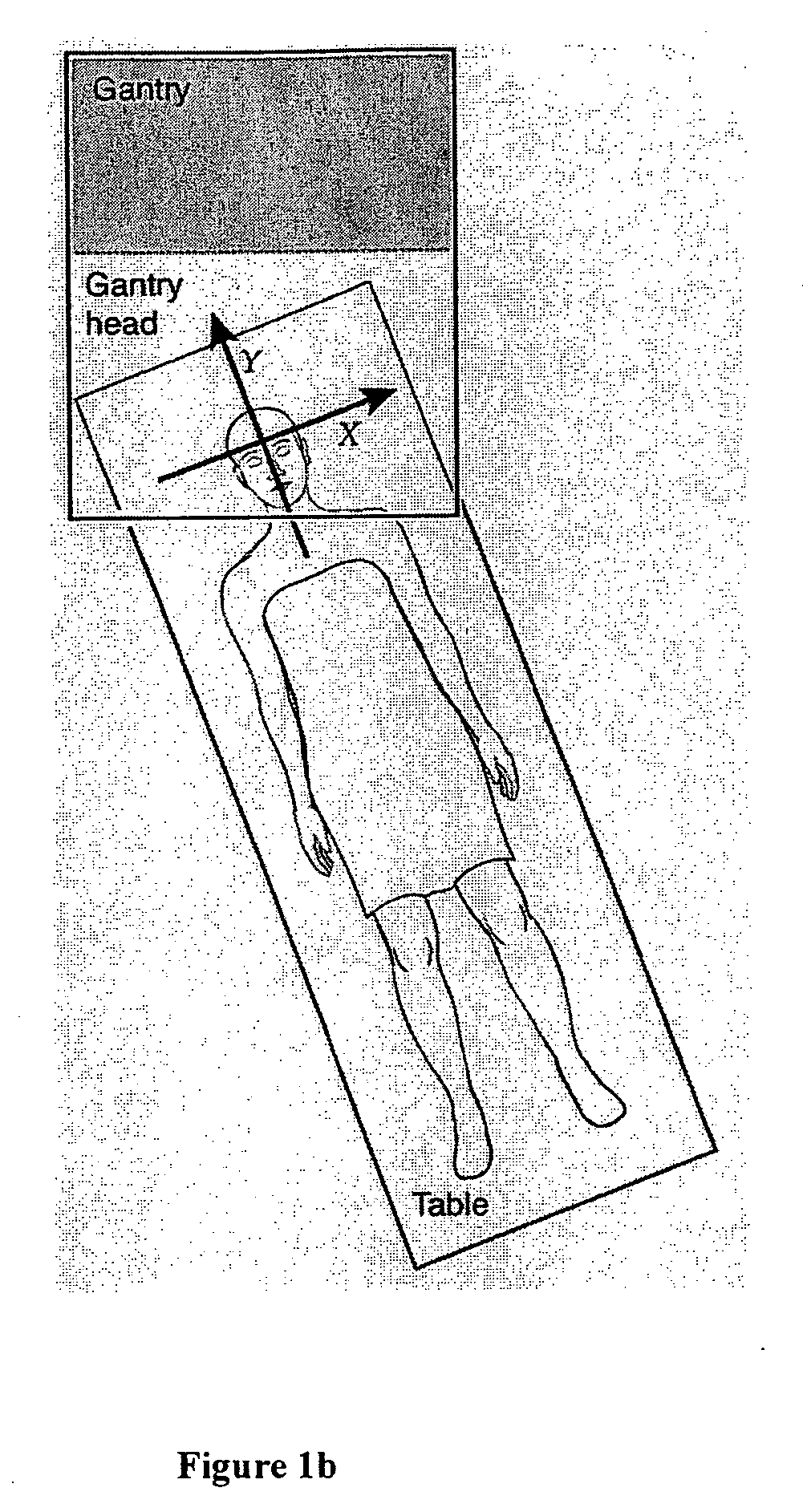
[0009] Generally, the methods of the present invention provide transformations that facilitate the correction of target position variations between a patient's planned treatment and the actual treatment positions at the time of treatment and restore the original beam geometries relative to the patient's planned treatment. The invention utilizes three matrix transformations: 1) transformation of beams from the machine coordinate system to the patient coordinate system as provided in a patient geometry in the approved dosimetric plan; 2) transformation of beams from the patient coordinate system in the approved radiotherapy plan to the patient coordinate system that is identified at the time of treatment; and 3) transformation of beams from the patient coordinate system at the time of treatment in the treatment patient geometry back to the machine coordinate system. In the present invention it is preferable that the transformation matrix used for the second transformation is determined through the use of image-guided radiotherapy technology. Use of the image-guided radiotherapy facilitates correction. However, other methods are available such as the fixed point, described hereinafter, but which are slower.
[0010] By using these matrix transformations, the isocenter coordinates, the gantry, couch and collimator angles of the beams for the treatment, adjusted for any shift in the location of the target can be derived. Utilizing the transforms, new beam parameters can be determined that will possess the same positions and orientations relative to the patient target as provided in the treatment plan. This is generally achieved by adjusting the patient treatment couch, and setting the beams in the newly derived gantry, collimator, and couch angles, so that any changes in the patient target location that occur between the time of the plan and the time of treatment can be fully corrected.

Problems solved by technology

However, other methods are available such as the fixed point, described hereinafter, but which are slower.

Method used


Image

  • Method to implement full six-degree target shift corrections in radiotherapy
  • Method to implement full six-degree target shift corrections in radiotherapy
  • Method to implement full six-degree target shift corrections in radiotherapy

Examples


example

[0065] The method of the presently preferred embodiment was utilized in a phantom case. FIGS. 3 and 4 depict the results.

[0066] In this example, a brain tumor patient was treated with 3-D conformal radiation therapy. A set of CT scans were acquired before treatment for the purpose of treatment planning. A treatment plan was designed based on the CT scans (using Varian Eclipse™ treatment planning system) and three 6 MV photon beams were used. These three beams are labeled as field 1, field 2, and field 3, respectively. Beam portals of field 1, field 2 and field 3 on the corresponding digitally reconstructed radiographs (DRR) are shown in FIGS. 3a—a, 3b—a, and 3c—a, respectively. Some of the planned beam parameters are also listed in Table 1. A set of CT scans (“treatment” verification CT scan) were acquired using a CT simulator with the patient in the treatment setup position as determined in the treatment plan. A facial mask was used as a fixation device. The three beam portals of ...


PUM


Abstract

The invention provides a method using matrix transformations of the three coordinate systems used in radiotherapy to correct for any deviation between a planned dosemetric treatment target and the actual location of the treatment target.

Description

FIELD OF THE INVENTION [0001] The present invention relates to a method to correct errors introduced by movement of the targeted area of radiation beams, and in particular to a method using transformation matrices to correct for image target movements from planned target locations used in image guided radiotherapy. BACKGROUND OF THE INVENTION [0002] Generally, the present invention relates to radiotherapy and more particularly to a procedure that creates a three dimensional picture of a location or area in the body of a patient to be treated, such as a tumor. Radiotherapy generally involves the use of an external beam with a linear accelerator, which largely delivers photons (γ-radiation). Neutron beam radiotherapy is used for some tumors with a narrow tissue margin. Electron beam radiotherapy has a very short tissue penetration and is typically used for skin or superficial cancers. Proton therapy can provide very narrow depth of field exposure with sharp margins. [0003] Typically t...

Claims


Application Information

Patent Timeline
Patent Type & Authority Applications(United States)
IPC IPC(8): A61B6/08
CPCA61N5/1049A61N2005/1061A61N5/1069A61N5/1065
Inventor YUE, NING J.
Owner UPMC
Learn More