Suspension structure for wheelchair

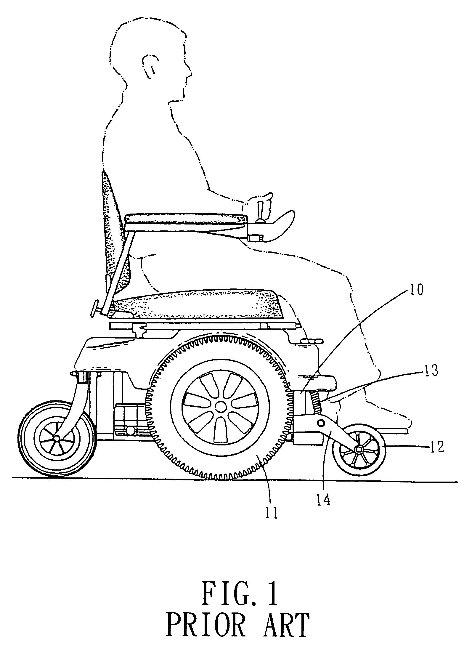
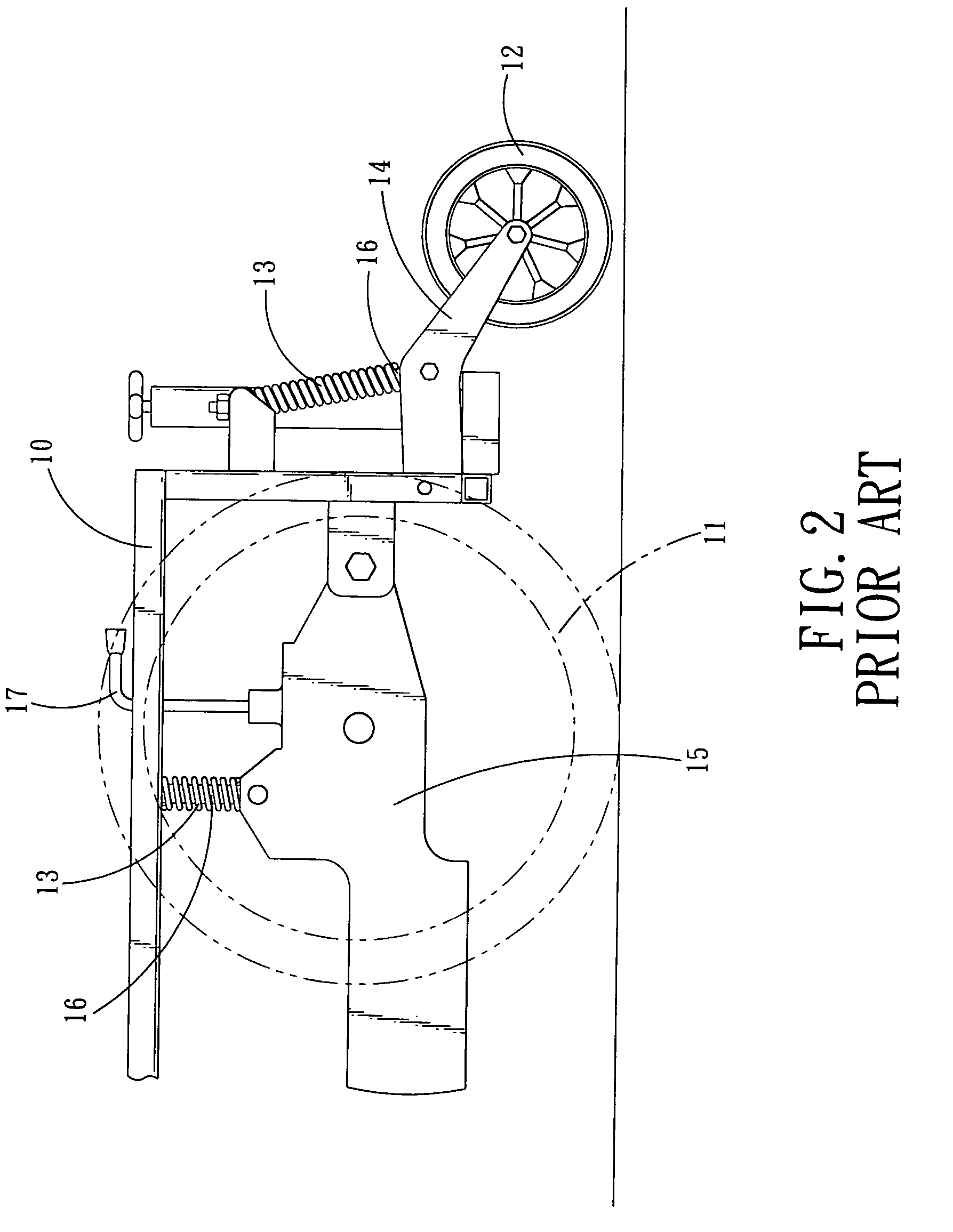
a suspension structure and wheelchair technology, applied in the direction of wheelchairs/patient conveyances, chairs, sofas, etc., can solve the problems of wheelchairs not being easy to roll over the barrier, the friction of the driving wheel and the road cannot be increased correspondingly, and the respective compression springs b>13/b> also have elastic fatigue problems

Inactive Publication Date: 2006-04-04
PIHSIANG MACHINERY MFG
View PDF22 Cites 83 Cited by
  • Summary
  • Abstract
  • Description
  • Claims
  • Application Information

AI Technical Summary

Benefits of technology

[0009]The primary object of the present invention is to provide a suspension structure for wheelchair, which generally includes movable arm that serves to connect driving wheels with frame of a wheelchair, sliding unit is further provided for enabling the movable arm to movably connect with a front cantilever of the wheelchair. By such arrangements, upon encountering a raised ground, or similar barriers of the like, the front cantilever will work with the movable arm to raise the front jockey wheel, whereas the driving wheels firmly catches the ground, so as to enable the wheelchair to the pass the barrier smoothly without difficulties.

Problems solved by technology

However, there are some deficiencies will be found in real operation:
Moreover, the respective compression springs 13 also have elastic fatigue problem.
Second, when faced with a barrier and the front jockey wheel 12 is stopped by resistance (when the front jockey wheel abuts against slopping surface of the barrier), since the suspension structures of the front jockey wheel 12 and that of the driving wheel 11 are not interactively connected, the friction of the driving wheel with the road can not be increased correspondingly, in this case, the wheelchair is not easy to roll over the barrier.
Third, since the compression springs 13 serve as suspension structure for the driving wheel 11 and the front jockey wheel 12, the suspension structure is very complexly designed as comprising at least a pair of front cantilevers 14, a pair of drive rods 15, four pieces of compression spring 13 and shafts 16, a pair of stop rods 17. Thus the cost is pretty high.

Method used


Image

  • Suspension structure for wheelchair
  • Suspension structure for wheelchair
  • Suspension structure for wheelchair

Examples


Embodiment Construction

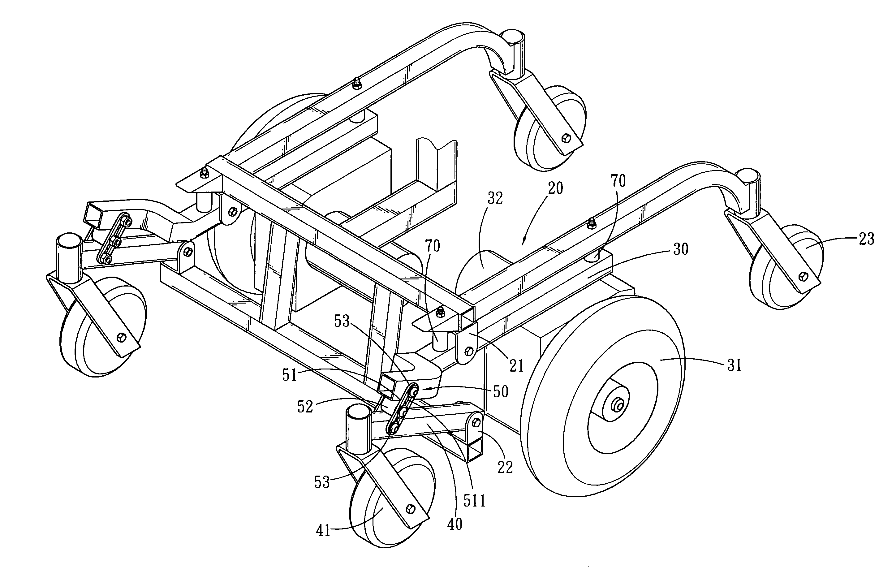
[0020]Referring to FIGS. 3–5, wherein a suspension structure for wheelchair is shown and comprised of movable arm 30, front cantilever 40 and a sliding assembly 50 which are respectively provided between frame 20, driving wheel 31 and front jockey wheel 41.

[0021]The frame 20 is main body of a wheelchair and serves to carry respective components of the wheelchair. The front side of the frame can be provided with a first ear 21 and a second ear 22, the rear end of the frame can be equipped with rear wheel 23.

[0022]The movable arm 30 is swingingly coupled to the first ear 21 of the frame 20. An end of the movable arm 30 is connected to the driving wheel 31, the driving wheel 31 is driven by a motor 32 to move the wheelchair.

[0023]The front cantilever 40, a first end of which is equipped with the front jockey wheel 41 and a second of the front cantilever 40 is fixed to the second ear 22 of the frame, thus the front cantilever 40 is able to swing.

[0024]The sliding assembly 50 includes a ...


PUM


Abstract

A suspension structure for a wheelchair generally includes movable arm that serve to connect driving wheels with frame of a wheelchair, sliding unit is further provided for enabling the movable arm to movably connect with a front cantilever of the wheelchair. By such arrangements, in case that the wheelchair of the present invention encounters a raised ground, or similar barriers of the like, the front cantilever will work with the movable arm to raise front jockey wheels, whereas the driving wheels firmly catches the ground, such that enables the wheelchair to the pass the barrier smoothly without difficulties.

Description

BACKGROUND OF THE INVENTION[0001]1. Field of the Invention[0002]The present invention relates to a suspension structure for a wheelchair, and more particularly to a suspension structure comprised of front cantilever, movable arm and sliding assembly, which are provided between front jockey wheel, driving wheel and frame of a wheelchair.[0003]2. Description of the Prior Arts[0004]A conventional wheelchair with suspension structure as shown in FIGS. 1 and 2 (as disclosed by U.S. Pat. No. 6,199,647), wherein between a frame 10, driving wheel 11 and front jockey wheel 12 is provided with plural compression springs 13, the compression springs 13 serve to timely raise or lower down the front jockey wheel 12 and the driving wheel 11 upon encountering a raised ground, or similar barrier of the like, so as to enable the wheelchair to overcome the barrier. However, there are some deficiencies will be found in real operation:[0005]First, the front jockey wheel 12 and the driving wheel 11 are i...

Claims


Application Information

Patent Timeline
Patent Type & Authority Patents(United States)
IPC IPC(8): B62M1/14A47C20/00B60K1/00A61G5/04A61G1/02A61G5/02A61G5/06A61G5/10
CPCA61G5/042A61G5/043A61G5/06Y10S280/10A61G2005/1078A61G5/1078
Inventor WU, DONALD P. H.
Owner PIHSIANG MACHINERY MFG
Why Eureka
Try Eureka