[0009]The locking position of the actuating element clearly differs from the retaining position. It is similar to the retaining position inasmuch as also in the locking position the locking elements are in a locking configuration preventing a disconnection of the coupling parts. However, unlike in the retaining position of the actuating element, for the release of the coupling no simple movement into the release position is possible and instead a more complex movement sequence is required, in which normally the actuating element must initially be moved back into the retaining position and then into the release position. It is improbable and excluded in practice that these two movements, which preferably are in opposite directions, are unintentionally performed or are initiated by chance due to external effects. Thus, fluid coupling devices equipped with the coupling parts according to the invention are particularly reliable in operation, without their handling being made significantly more complicated.
[0010]The invention can e.g. be implemented with quick couplings of the type disclosed by DE 34 90 017, in which the actuating member is actively brought into the release position for coupling in and must then be moved into its retaining position for locking the coupling parts. However, particular preference is given to embodiments in which the coupling parts can be brought into the coupling position without actuation and / or movement of the actuating element, because as a result the fitting together of the coupling parts can take place particularly rapidly and easily. Thus, the invention can be used with particular
advantage in all quick coupling embodiments described in exemplified manner in DE 17 75 302, whose features are, by reference, made into part of the content of this description.
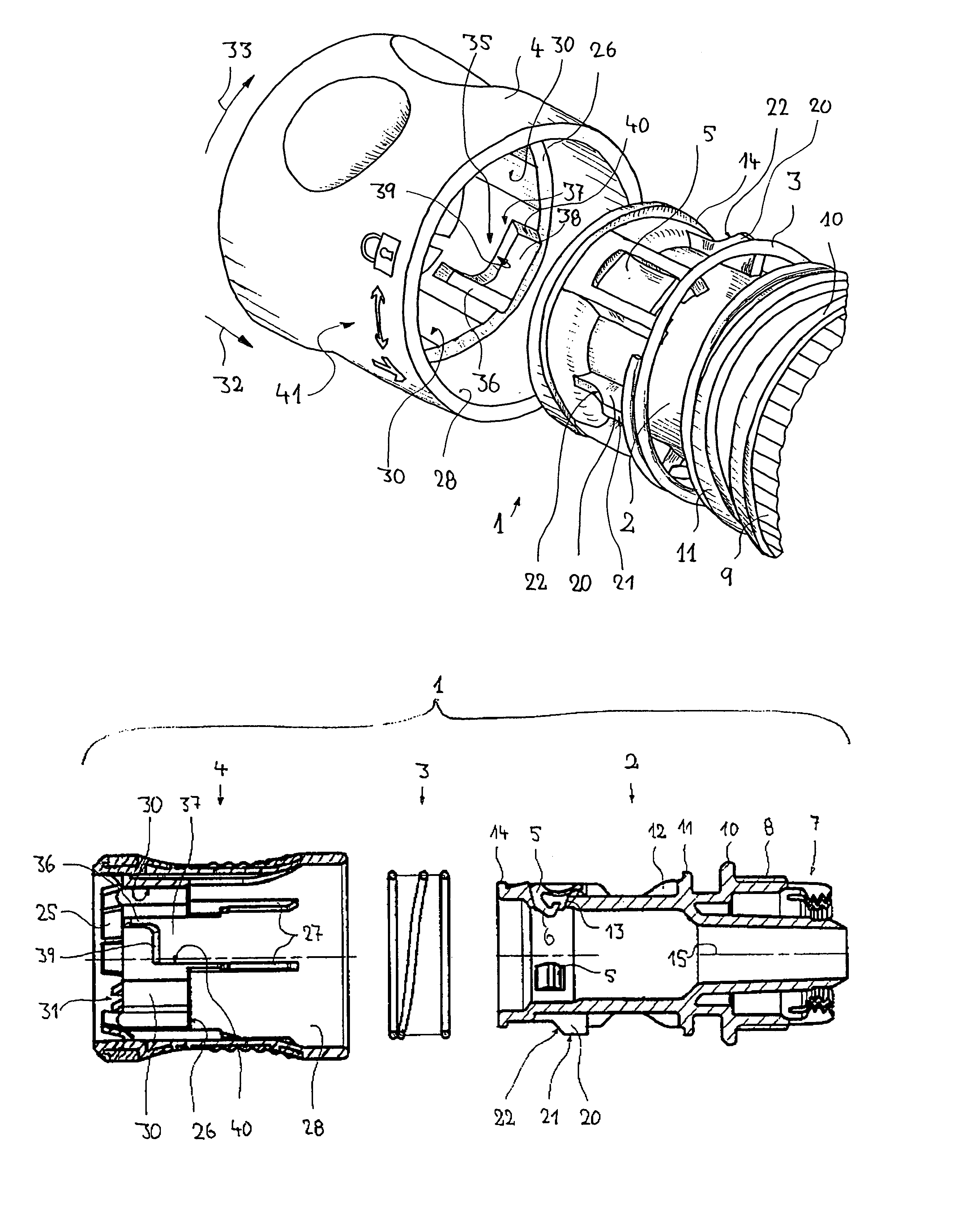
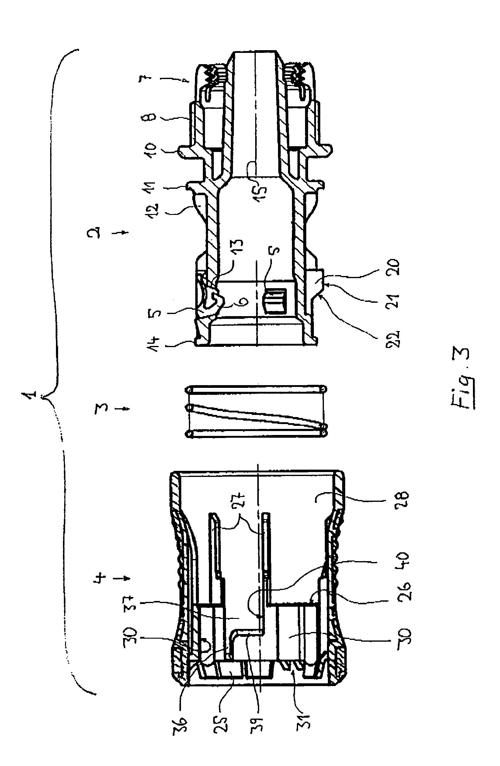
[0011]Therefore the situation can be such that the coupling part has a main or basic body, in which are provided several, e.g. three locking elements arranged around the circumference of the main body. The locking elements are preferably in the form of separate insert bodies, which are guided in axially fixed manner in openings of the main body and which in each case have
cam sections provided for engaging on one another under the action of spring tension in an e.g. annular groove-like recess of the other coupling part, e.g. a hose nipple, for the purpose of locking together the coupling parts. On both axial faces the
cam section appropriately has inclined surfaces in the manner of
insertion bevels, so that inter alia the fitting together of the coupling parts without actuation or movement of the actuating element is aided. The actuating element is preferably an actuating sleeve which embraces the basic body at least in the vicinity of the locking elements and which has on its inside closing faces, which cooperate with the radial outsides or backs of the locking elements in such a way that in the retaining position of the sleeve the locking elements are radially supported to the outside and are so wedged between the inner part and the closing face that an outward movement is largely prevented, whereas in the sleeve release position an outward movement is possible permitting the pulling apart of the coupling parts. The switching between the retaining and release positions can take place by rotating the sleeve about its longitudinal axis or by axial sleeve displacement and in particular in the case of axial displaceability of the actuating sleeve between the retaining and release positions, a one-handed operation of the coupling is easily possible.
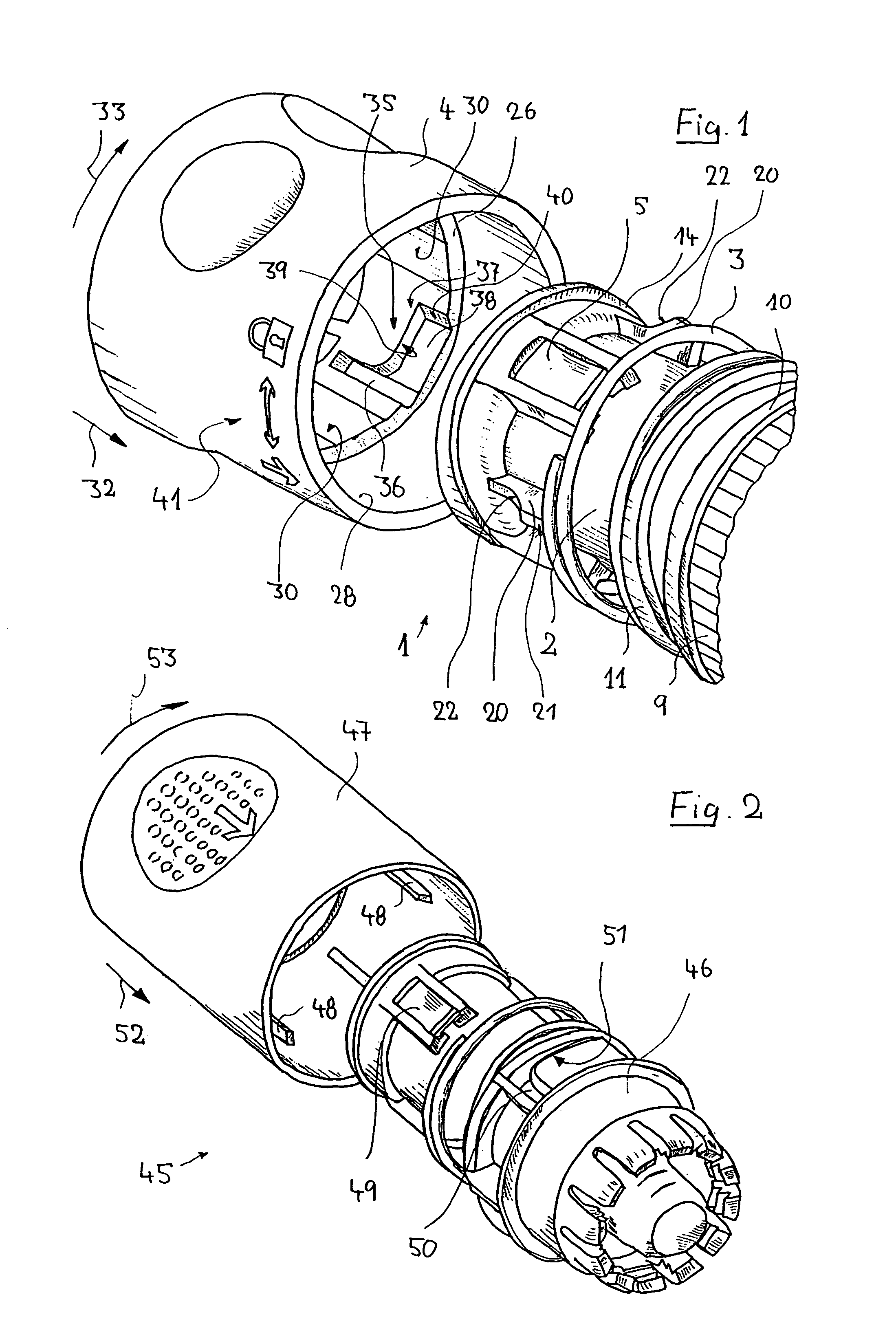
[0012]The preferably sleeve-like actuating element, although it can have a non-sleeve shape, is consequently preferably movably arranged with respect to the basic body of the coupling part, is preferably pretensioned in its retaining position and for releasing the coupling can be moved from the retaining position into the release position in a release direction, which is preferably the longitudinal direction of the coupling part or basic body. A particularly simple operation of the locking means is brought about in that the actuating element can be moved from the retaining position into the locking position by moving in a release direction at right angles and in particular perpendicular thereto. This locking direction is, in the case of a longitudinally displaceable actuating element, preferably the circumferential direction of the coupling, so that for locking the actuating element must be turned about the longitudinal axis of the coupling, starting from the retaining position. In the case of actuating elements, whose rotation brings about a coupling release, the setting of the locking position can take place correspondingly, e.g. by a longitudinal displacement of the actuating element.
[0017]To aid easy, faultless operation an indicating device can be provided, with the aid of which the blocked or unblocked state of the coupling can be rendered optically visible. For example, on the basic body and on the actuating element can be applied marks or signs, e.g. by imprints, whose relative position differs in the blocked and unblocked state.
[0018]
Operational reliability and security can be increased in that latching means are provided for the latching securing of the actuating element in the retaining position and in the locking position and which are constructed in such a way that the actuating element can only be shifted between the retaining position and locking position by overcoming a latching resistance. Thus, both an undesired locking of the coupling and also an undesired unlocking are made more difficult and the actuating element remains in stable form in the given position.

