Rocking-reclining seating unit with motion lock

a technology of motion lock and seating unit, which is applied in the field of seating units, can solve the problems of affecting the movement of the seating unit, and affecting the movement of the seat, so as to achieve the effect of improving the movement of the seating uni

Active Publication Date: 2006-04-04
ULTRA MEK
View PDF12 Cites 38 Cited by
  • Summary
  • Abstract
  • Description
  • Claims
  • Application Information

AI Technical Summary

Benefits of technology

[0005]The present invention is directed to aspects of a motion locking mechanism for a rocker-recliner seating units that may reduce cost and / or simplify assembly while still providing adequate performance. As a first aspect, embodiments of the present invention are directed to a rocking and reclining seating unit that includes: a base having first and second generally horizontal bearing surfaces; a generally horizontally-disposed seat positioned above the base; a generally upright backrest positioned above the base and substantially rearward of the seat; a reclining mechanism attached to the seat and the backrest for moving said seat and backrest between upright and reclined positions relative to the base, the reclining mechanism comprising a plurality of pivotally interconnected links; a rocker cam attached with the reclining mechanism, the rocker cam including an arcuate lower contact surface positioned to contact the first bearing surface, the lower contact surface being configured for rolling contact with the first bearing surface such that the seat has a rocking motion relative to the base; a rocker spring assembly that includes a resilient member that biases the seat against rocking motion relative to the base, the rocker spring assembly being attached with a respective reclining assembly and with the base; and a locking mechanism configured to prevent rocking motion of the seat relative to the base when the chair is in a reclined position, the locking mechanism being interconnected with the base and with the reclining mechanism. The locking mechanism includes: a drive link pivotally interconnected with the reclining mechanism; a control link pivotally interconnected with the base, the control link including a slot; and a bracing link pivotally and slidably interconnected with the control link via a pin mounted to the bracing link and inserted into the control link slot. The bracing link is further pivotally interconnected with the drive link and has an engagement end. The locking mechanism is movable between a retracted position, in which the engagement end of the bracing link does not engage the base to prevent rocking motion of the seating unit, and an extended position, in which the engagement end of the bracing link engages the second bearing surface of the base to prevent rocking movement of the seating unit. The locking unit is coupled with the reclining mechanism such that, when the seating unit is in the upright position, the locking mechanism is in the retracted position, and when the seating unit is in one of the reclined positions, the locking mechanism is in the extended position. This configuration can employ fewer parts and improve operation of the locking mechanism, particularly when the lock is in the open position.
[0008]As a third aspect, embodiments of the present invention are directed to a reclining seating unit for a rocking and reclining unit having: a base having first and second generally horizontal bearing surfaces; a generally horizontally-disposed seat positioned above the base; a generally upright backrest positioned above the base substantially rearward of the seat; a reclining mechanism for moving the seat and backrest between upright and reclined positions relative to the base, the reclining mechanism comprising a plurality of pivotally interconnected links and including a backpost fixed to the backrest and a transition plate pivotally interconnected to the backpost; a rocker cam attached with the reclining mechanism, the rocker cam including an arcuate lower contact surface positioned to contact the first bearing surface, the lower contact surface being configured for rolling contact with the first bearing surface such that the seat has a rocking motion relative to the base; a rocker spring assembly that includes a resilient member that biases said seat against rocking motion relative to said base, the rocker spring assembly being attached with a respective reclining mechanism and to the base; and a locking mechanism configured to prevent rocking motion of the seat relative to the base when the chair is in a reclined position, the locking unit being coupled with the reclining mechanism such that, when the seating unit is in the upright position, the locking mechanism is in the retracted position, and when the seating unit is in one of the reclined positions, the locking mechanism is in the extended position. The transition plate of the reclining mechanism includes a slot, and the backpost of the reclining mechanism includes a pin that extends into the transition plate slot. This configuration can improve movement of the seating unit from a fully reclined position to the upright position by controlling the sequence in which the links pivot as the ottoman returns from its extended position.

Problems solved by technology

Because the slotted link slides on the pin of the mounting bracket during the rocking motion, in some instances the occupant of the chair can rock forward sufficiently that the rear end of the slot strikes the pin, thereby giving a jolt to the occupant.
Also, because of the configuration of the locking mechanism, if the occupant is rocking forward when releasing the chair to a reclined position, in some instances the chair can “catch” and impede reclining movement.

Method used


Image

  • Rocking-reclining seating unit with motion lock
  • Rocking-reclining seating unit with motion lock
  • Rocking-reclining seating unit with motion lock

Examples


Embodiment Construction

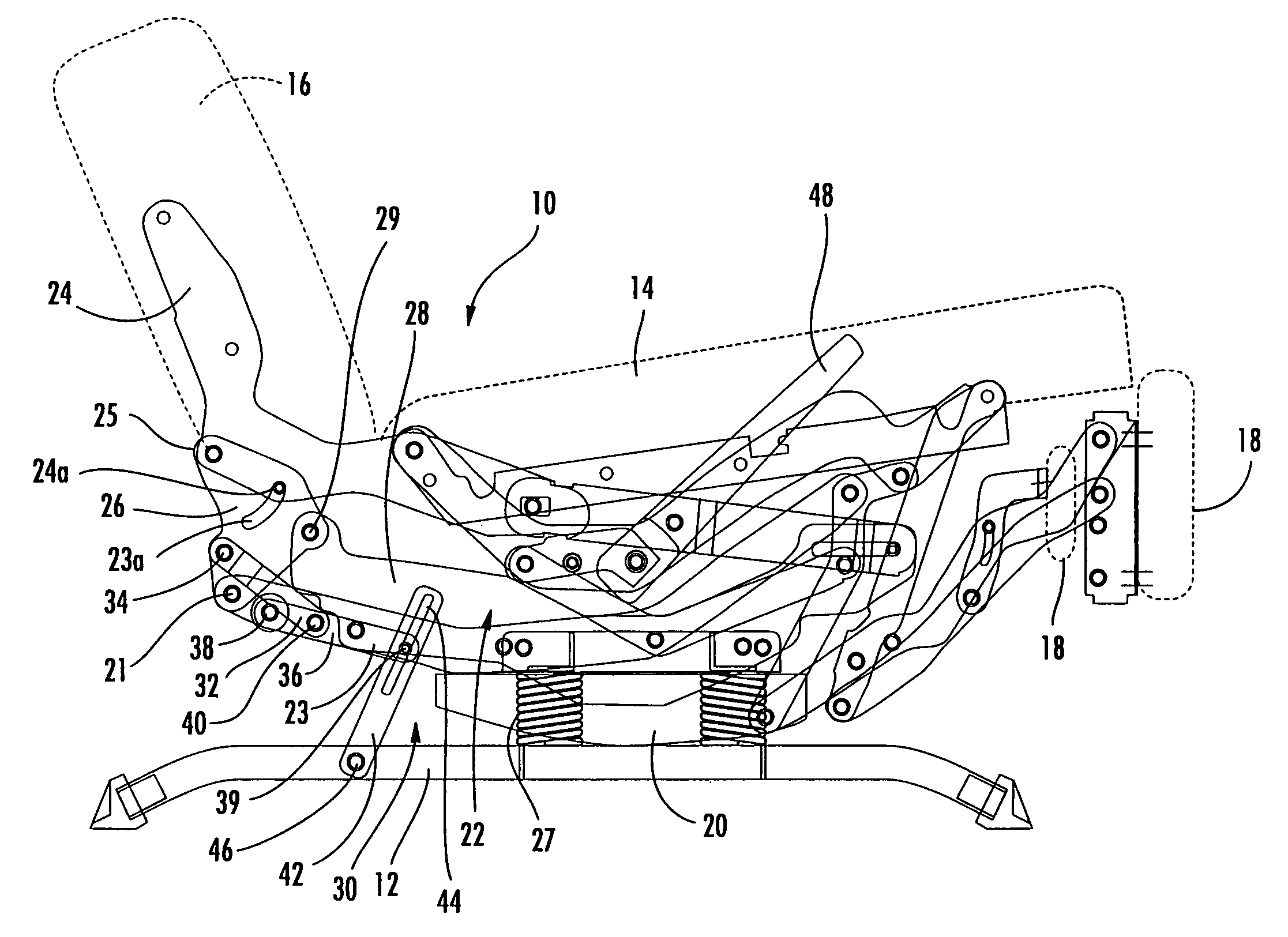
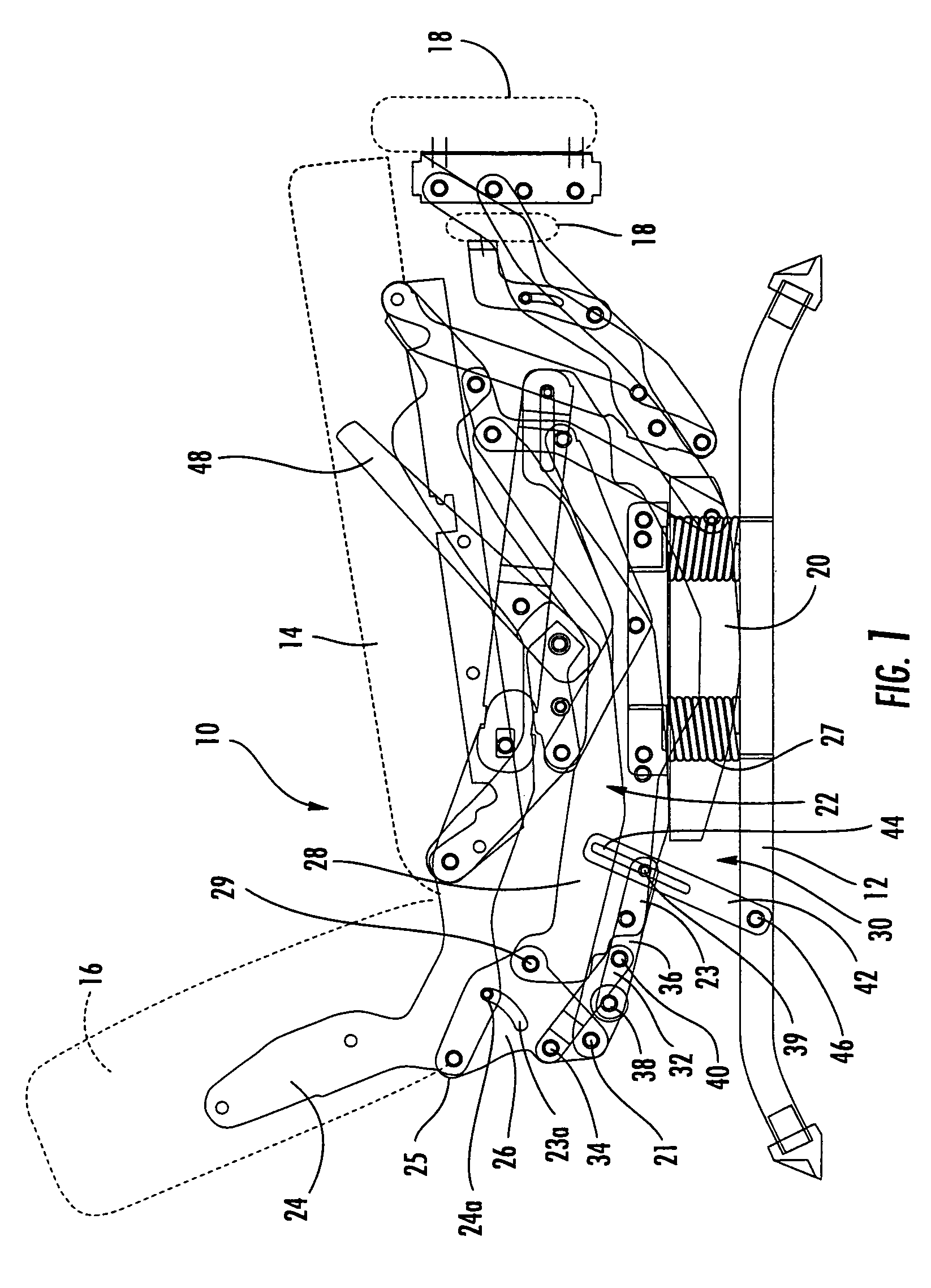
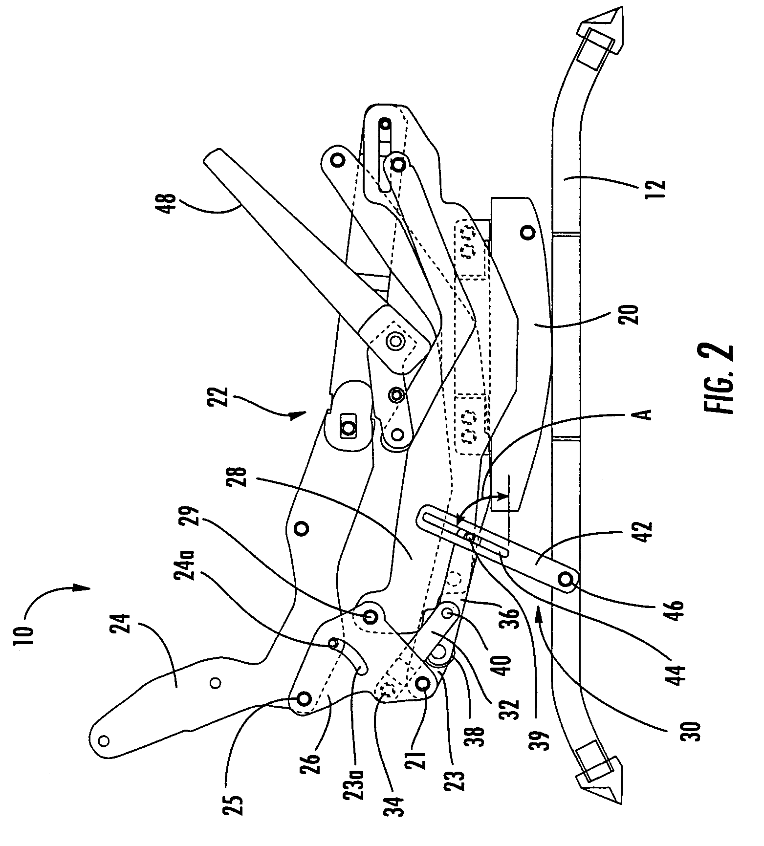
[0013]The present invention will be described more particularly hereinafter with reference to the accompanying drawings. The invention is not intended to be limited to the illustrated embodiments; rather, these embodiments are intended to fully and completely disclose the invention to those skilled in this art. In the drawings, like numbers refer to like elements throughout. Thicknesses and dimensions of some components may be exaggerated for clarity.

[0014]This invention is directed to seating units that have a stationary base, a seat portion, and a backrest. As used herein, the terms “forward”, “forwardly”, and “front” and derivatives thereof refer to the direction defined by a vector extending from the backrest toward the seat parallel to the underlying surface. Conversely, the terms “rearward”, “rearwardly”, and derivatives thereof refer to the direction directly opposite the forward direction; the rearward direction is defined by a vector that extends from the seat toward the ba...


PUM


Abstract

A locking mechanism configured to prevent rocking motion of a seat of a rocking and reclining chair relative to a base of the chair when the chair is in a reclined position, the locking mechanism being interconnected with the base and with a reclining mechanism of the chair, includes: a drive link adapted to be pivotally interconnected with the reclining mechanism; a control link adapted to be pivotally interconnected with the base and having a slot; and a bracing link pivotally interconnected with the drive link and slidably and pivotally interconnected with the control link via a pin inserted into the control link slot, the bracing link including a wheel at an engagement end thereof. The locking mechanism is configured to be movable between a retracted position, in which the engagement end of the bracing link does not engage the base to prevent rocking motion of the chair, and an extended position, in which the engagement end of the bracing link engages a bearing surface of the base to prevent rocking movement of the chair.

Description

FIELD OF THE INVENTION[0001]This invention relates generally to seating units, and relates more particularly to reclining seating units with rocking capability.BACKGROUND OF THE INVENTION[0002]Recliner chairs and other reclining seating units have proven to be popular with consumers. These seating units typically move from an upright position, in which the backrest is generally upright, to one or more reclined positions, in which the backrest pivots to be less upright. The movement of the seating unit between the upright and reclined positions is typically controlled by a pair of matching reclining mechanisms that are attached to the seat, backrest and base of the chair.[0003]One particularly popular reclining chair is the so-called “rocker-recliner,” which can, when in the upright position, rock with a forward and rearward motion similar to that of a traditional rocking chair. A typical rocker recliner, one of which is illustrated in U.S. Pat. No. 4,519,647 to Rogers, includes an a...

Claims


Application Information

Patent Timeline
Patent Type & Authority Patents(United States)
IPC IPC(8): A47C3/03
CPCA47C1/0355A47C3/027Y10S297/07
Inventor HOFFMAN, D. STEPHENMURPHY, MARCUS L.
Owner ULTRA MEK
Why Eureka
Try Eureka