
Plug-in connector

a plug-in connector and connector technology, applied in the direction of securing/insulating coupling contact members, coupling device connections, electrical devices, etc., can solve the problems of inaccuracy and significant cost, and achieve the effect of wide width

Active Publication Date: 2006-04-04
ERNI PRODION GMBH
View PDF5 Cites 71 Cited by
  • Summary
  • Abstract
  • Description
  • Claims
  • Application Information

AI Technical Summary

Benefits of technology

[0013]Preferably, the insertion region of the one contact element is thinner than the insertion region of the other contact element. The advantage of the invention consists in the fact that all of the insertion chambers in the housing of the plug-in connector have the same shape, so that production is facilitated and different contact elements having different insertion regions can be inserted into the same insertion chamber without additional machining.
[0014]Preferably, at least two different contact elements can be optionally inserted into one insertion chamber, in each instance, of a plug-in connector, whereby the contact elements have an insertion region, in each instance, that is configured to be differently broad and / or thick. If the insertion chamber is appropriately configured, however, even three or more different contact elements can be optionally inserted into the plug-in connector, depending on the specific requirements of the connector.
[0015]The insertion region of an electrical contact element has a rectangular cross-section in the axial direction, seen in the longitudinal expanse of the element. This results from the fact that the electrical contact elements are obtained in known manner, in a punching process, from a sheet-metal cut-out, so that this insertion region has the thickness of the original sheet-metal cut-out.
[0016]For the contact elements, a rectangular or square insertion chamber having grooves that correspond to one another on its sides that lie opposite one another is provided, so that during the insertion of each contact element, this rectangular insertion region is brought into engagement with the grooves and held there by means of a positive lock. Several different grooves that correspond to one another can be arranged on two opposite sides of the insertion chamber, or a specific groove can even be provided in pairs on two opposite sides. Thereby two contact elements having different insertion regions could be inserted into the different insertion chambers at a 90° angle relative to one another, for example.
[0017]In an advantageous further development of the invention, an additional, accordingly narrower groove is made in the bottom of a groove for accommodating an insertion region having a rectangular cross-section. This additional groove serves to accommodate a narrower, i.e. thinner insertion region of another contact element, with reference to the groove originally made. Preferably, such additional grooves are formed on two grooves that lie opposite one another, on two sides of a rectangular insertion chamber. With these additional grooves, it is possible that either a contact element having an insertion region having a large width can be inserted, or a contact element having an insertion chamber having a narrower cross-section can be inserted into the additional, narrower grooves, into one and the same insertion chamber. If a contact element having a broad cross-section is inserted into the insertion chamber, then this insertion region covers the additional, narrower groove made in the first groove. The grooves can be formed over the entire insertion depth of the insertion chamber, or only in segments, seen in the insertion direction.
[0018]Because of the production accuracies that can be achieved, it is possible to select the differences in the widths or thicknesses of the insertion regions of different contact elements, preferably in the range of 1 / 10 mm, so that even special contact elements, which are obtained from sheet-metal cut-outs having only a slightly different material thickness, can be inserted into the insertion chamber, according to the invention, of a housing of a plug-in connector.

Problems solved by technology

This is connected with significant costs as a result of the additional machining step, and can also result in inaccuracies in the fit.

Method used


Image

  • Plug-in connector
  • Plug-in connector
  • Plug-in connector

Examples


Embodiment Construction

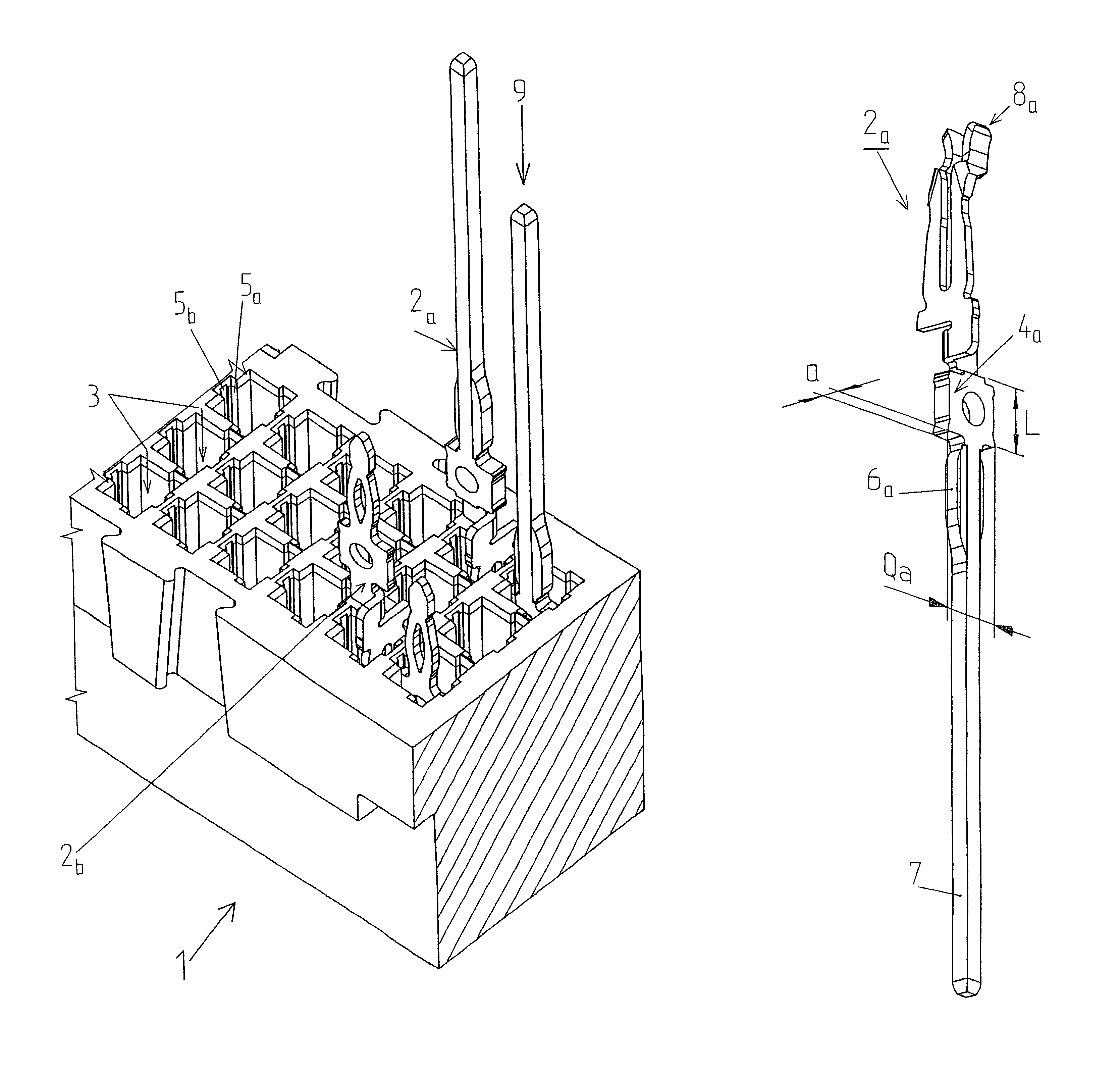
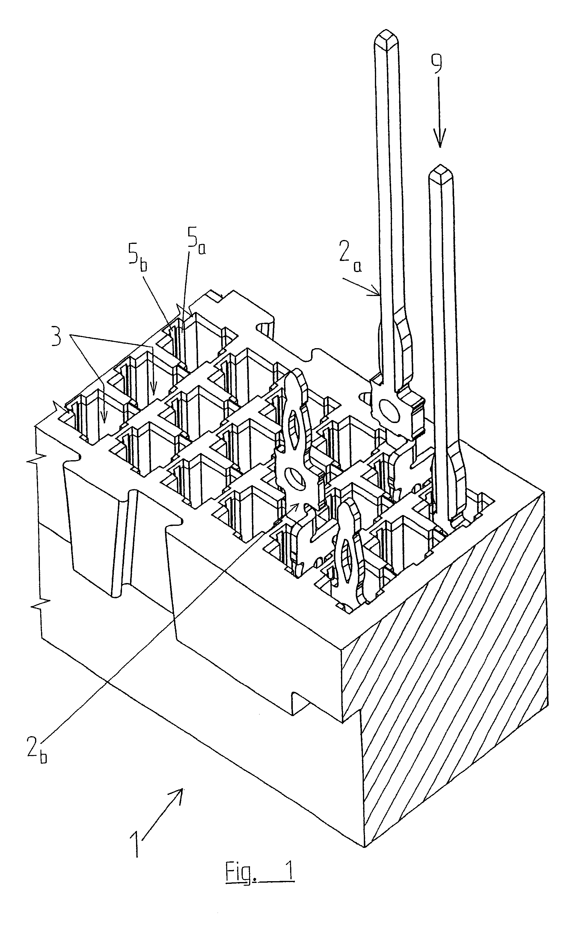
[0028]The exemplary embodiment of the invention shown in FIG. 1 is a housing 1 of a plug-in connector, particularly a male or female multi-point plug. These plug-in connectors meet certain DIN standards, whereby different contact elements 2a and 2b are inserted into housing 1, at the plug-in spot in housing 1. For example, contact elements 2a that have a shorter contact region 6 and a long, pin-shaped guide segment 7 that directly follows the latter, or other contact elements 2b, which possess a short contact region 6b of a different shape, can be used.

[0029]For stability reasons, contact elements 2a are made from a heavier, i.e. thicker material than the other contact elements 2b having the short contact region 6, in order to avoid bending of the long guide segment 7 when it is plugged onto another connection element or a circuit board or card.

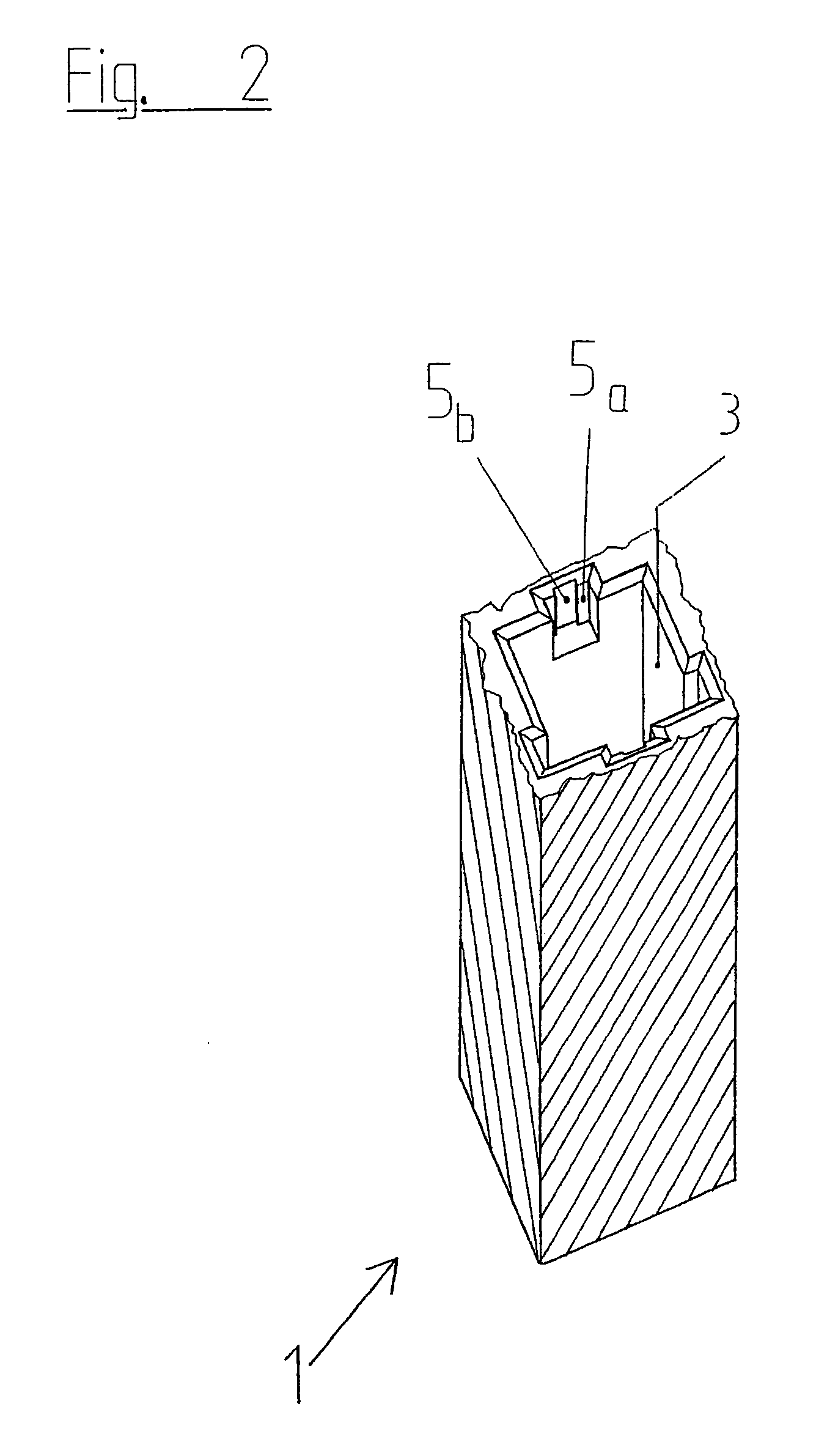
[0030]In order to align and hold contact elements 2a and 2b in housing 1, in each instance, in the desired position, an insertion region 4a ...


PUM


Abstract

A plug-in connector having a housing, particularly a multi-pole, multi-row male or female multi-point plug, whereby the housing is provided with insertion chambers for inserting electrical contact elements. In order to be able to insert different contact elements into one and the same insertion chamber in the housing, this insertion chamber is configured to accommodate different insertion regions.

Description

BACKGROUND OF THE INVENTION[0001]1. Field of the Invention[0002]The present invention finds use in plug-in connectors whose housing has at least one insertion chamber for accommodating contact elements.[0003]2. The Prior Art[0004]Plug-in connectors having a housing are known. In this connection, several electrical contact elements are usually arranged in the housing, in several rows that are parallel to one another, for example, 96 electrical contact elements in three rows. These plug-in connectors correspond to specific DIN standards.[0005]The housing consists of an injection-molded part made of plastic, into which the electrical contact elements can be inserted. These electrical contact elements can be configured in such a manner that they are completely inserted into the housing at one end, from one side, and are configured there in the form of a spring, into which another electrical contact element can be brought into engagement, which is inserted into the housing from the other...

Claims


Application Information

Patent Timeline
IPC IPC(8): H01R13/40H01R12/58H01R13/41
CPCH01R13/41Y10S439/943
Inventor LAPPOHN, JURGEN
Owner ERNI PRODION GMBH
Features
  • Generate Ideas
  • Intellectual Property
  • Life Sciences
  • Materials
  • Tech Scout
  • Unparalleled Data Quality
  • Higher Quality Content
  • 60% Fewer Hallucinations
Learn More