Filtration device

Inactive Publication Date: 2006-04-04
P & W INVEST VERMOEGENS VERW
View PDF9 Cites 21 Cited by
  • Summary
  • Abstract
  • Description
  • Claims
  • Application Information

AI Technical Summary

Benefits of technology

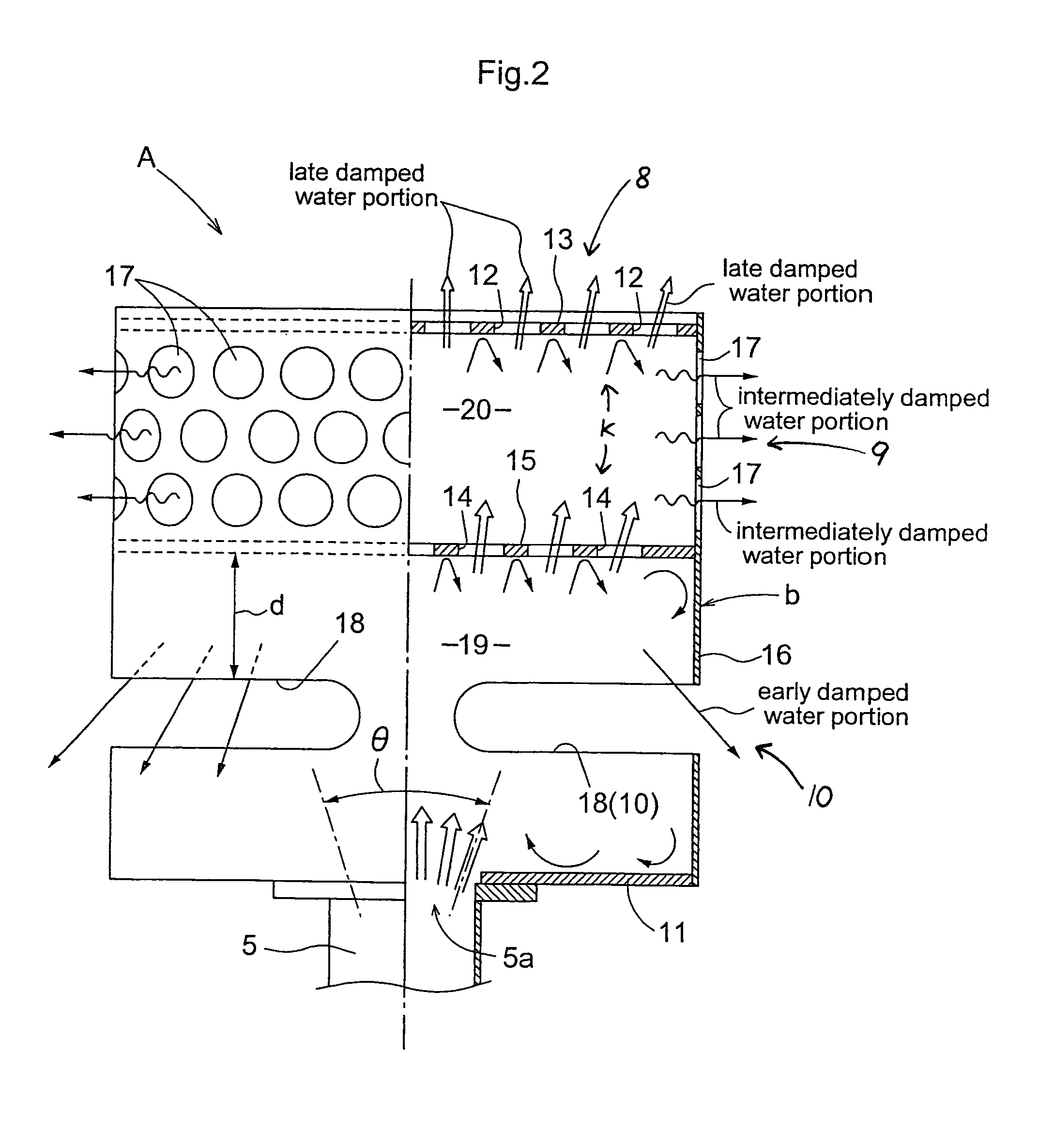
[0025]As illustrated in FIG. 3a and FIG. 3b, the holes 14 defined in the partitioning member 15 and the holes 12 defined in the top face member 13 are arranged so as not be overlapped in a plan view.
[0026]The holes disposed vertically relative to each other are so arranged not to be overlapped with each other in the plan view. This arrangement makes it difficult for the liquid discharged from the orifice to pass the holes at these two upper and lower positions smoothly without any interference. In other words, the arrangement can ensure that the liquid just passing the holes 14 of the partitioning member 15 may be reliably guided so as to subsequently collide against the bottom face of the top face member 1

Problems solved by technology

As a result, the flatness of the top surface of the filter medium layer 4 tends to be impaired, thus tending to invite insufficient filtering performance of the filter medium layer 4.
Therefore, with such reduction in the weight of the filter medium, even with the discharging speed of water remaining the same as before, the surface of the filter medium tends to be disturbed to impair the flatness of the top face of the filter media.
Hence, concentration of the filtering liquid occurs at the bottomed or lowered areas in the filter media surface, thus resulting in deterioration of filtering precision as well as reduction in the ef

Method used


Image

  • Filtration device
  • Filtration device
  • Filtration device

Examples


Embodiment Construction

Of THE INVENTION

[0039]For describing the invention in greater details, the invention will be described with reference to the accompanying drawings.

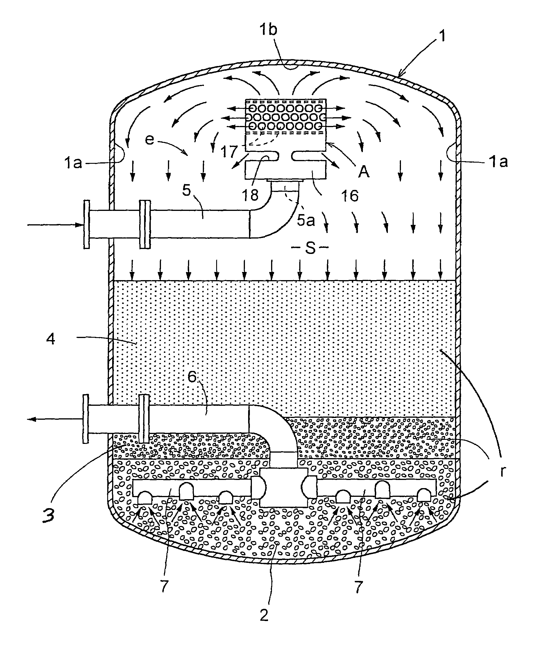
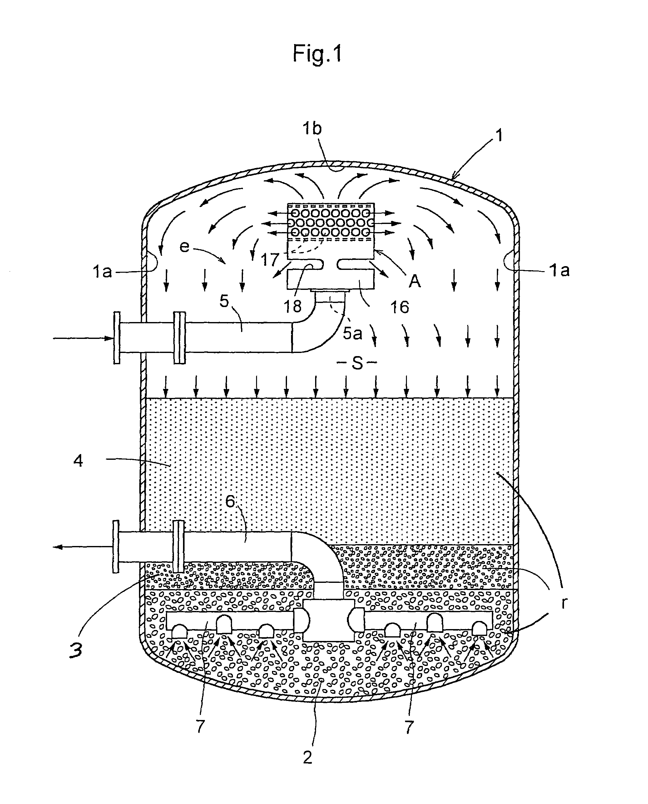
[0040]A water filtering apparatus shown in FIG. 1 includes, within a filtering tower 1 formed like a closed cylinder, a filtering section (r) comprising a first support silica rock layer 2, a second support silica rock layer 3 and a filter medium layer 4 stacked from the bottom to the top in the mentioned order, a water-reserving space S formed upwardly of the filter medium layer 4 and a liquid feeding section (e) provided upwardly of the filtering section (r).

[0041]The liquid feeding section (e) includes, within the water-reserving space S, a horizontally oriented inlet pipe (an example of “liquid feeding pipe”) 5 inserted into the filtering tower 1 through a lateral wall 1a of the tower 1 and having an upwardly directed orifice 5a at the leading end thereof, and a diffuser A for acting on water as being upwardly discharged from the orif...


PUM


Abstract

The invention relates to a filtering apparatus including, inside a filtering tower (1), a filtering section (r), a liquid collecting section (7) and a liquid feeding section (e). The liquid feeding section (e) includes a diffuser (A) attached to an upwardly oriented orifice (5a) formed at a leading end of a liquid feeding pipe (5). The object is to provide an apparatus which allows use of the existing filtering tower without its enlargement and which allows uniform falling of the filtering liquid over the substantially entire top surface of the filter medium layer, thus making it readily possible to maintain the flatness of the top surface of the filter medium layer even when light-weight medium is employed, thereby to allow the filter medium layer as well as the entire filtering apparatus to achieve their desired filtering performance. The diffuser (A) includes a damping portion (k) for damping the momentum of the liquid discharged from the orifice (5a), a first discharging portion (8) for upwardly discharging the liquid damped by the damping portion (k), a second discharging portion (9) for laterally discharging the liquid damped by the damping portion (k), and a third discharging portion (10) for downwardly discharging the liquid damped by the damping portion (k), said first, second and third discharging portions being stacked one on another from the top to the bottom in the mentioned order.

Description

BACKGROUND OF THE INVENTION[0001]1. Field of the Invention[0002]The present invention relates to a filtering apparatus for filtering liquid such as water. More particularly, the invention relates to a technique for achieving efficient filtration wherein the momentum of the liquid discharged upward is effectively restricted within a small space, thereby to allow uniform infiltration of the liquid over a surface of a filter medium inside a relatively small filtering tower.[0003]2. Description of the Related Art[0004]A conventional filtering apparatus shown in FIG. 9 includes, within a filtering tower 1 having a lid, a filtering section (r) comprising a plurality of kinds of filter media, a liquid collecting section 7 disposed downwardly of the filtering section (r), and a liquid feeding section (e) disposed upwardly of the filtering section (r). The liquid feeding section (e) includes a liquid feeding pipe 5 inserted into the filtering tower 1 from the outside thereof and having an or...

Claims


Application Information

Patent Timeline
IPC IPC(8): B01D24/14B01D24/40
CPCB01D24/14B01D24/405
Inventor IMAI, FUMIHITOPOLAK, WALTER
Owner P & W INVEST VERMOEGENS VERW
Why Eureka
Try Eureka