Variable-gain constant-bandwidth transimpedance amplifier

Active Publication Date: 2006-04-04
MARVELL ASIA PTE LTD
View PDF22 Cites 42 Cited by
  • Summary
  • Abstract
  • Description
  • Claims
  • Application Information

AI Technical Summary

Benefits of technology

[0015]A transimpedance amplifier (TIA) circuit according to the present invention includes a first opamp having an input and an output. A second opamp has an input that communicates with the first opamp and an output. A first feedback path communicates with the input and the out

Problems solved by technology

At some point, this will cause oscillation.
At

Method used


Image

  • Variable-gain constant-bandwidth transimpedance amplifier
  • Variable-gain constant-bandwidth transimpedance amplifier
  • Variable-gain constant-bandwidth transimpedance amplifier

Examples


Embodiment Construction

[0038]The following description of the preferred embodiment(s) is merely exemplary in nature and is in no way intended to limit the invention, its application, or uses. For purposes of clarity, the same reference numbers will be used in the drawings to identify similar elements.

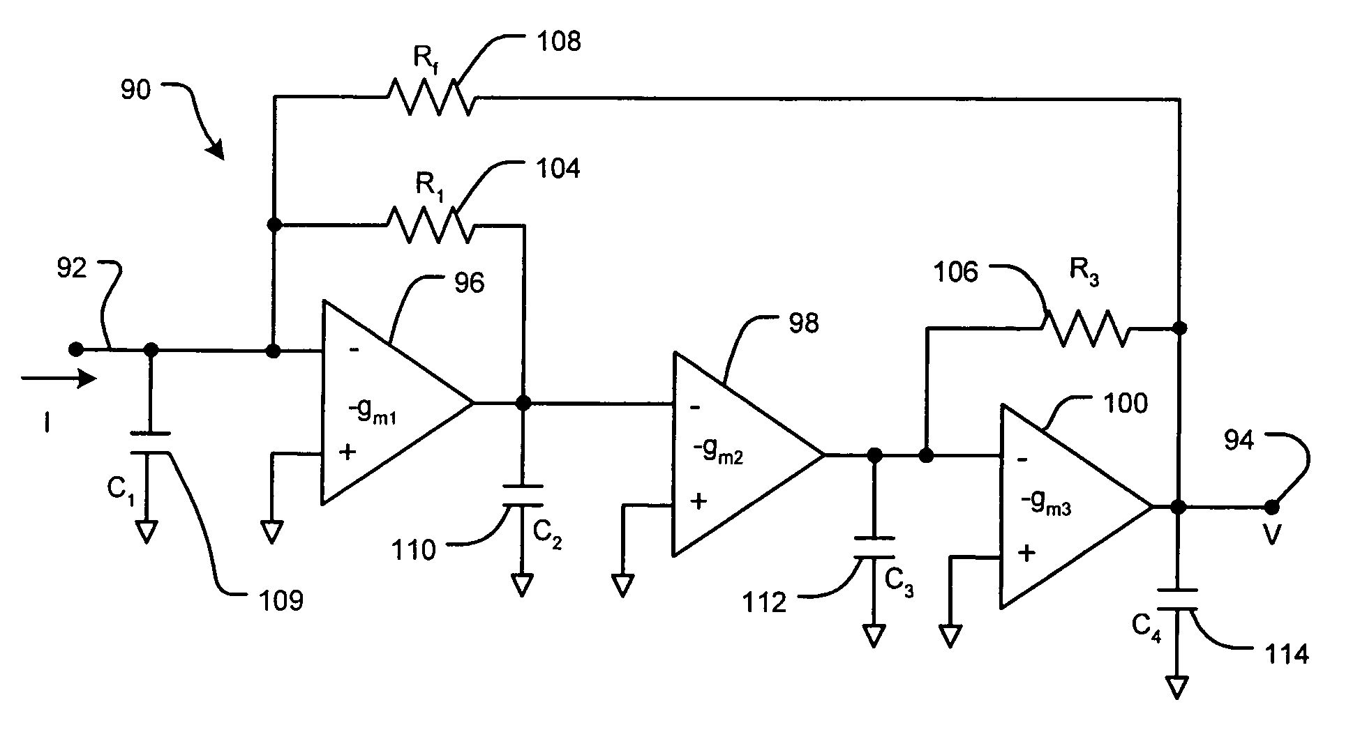
[0039]Referring now to FIG. 9, a multi-stage TIA 90 converts an input current I at 92 into an output voltage V at 94. The TIA 90 includes a first opamp 96, a second opamp 98 and a third opamp 100 that are coupled in series between the input and the output of the TIA 90. The opamps 96, 98 and 100 have transconductance values −gm1, −gm2 and −gm3, respectively. A resistance (R1) 104 is connected between the input and the output of the first opamp 96. Another resistance (R3) 106 is connected between the input and the output of the third opamp 100. A resistance (Rf) 108 is connected between the input and the output of the TIA 90. Capacitors and / or capacitances C1, C2, and C3 (109, 110, and 112, respectively) are c...


PUM


Abstract

A transimpedance amplifier (TIA) circuit according to the present invention includes a first opamp having an input and an output. A second opamp has an input that communicates with the first opamp and an output. A first feedback path communicates with the input and the output of the first opamp and includes a first resistance. A second feedback path communicates with the input and the output of the second opamp and includes a second resistance. A third feedback path communicates with the input of the first opamp and the output of the second opamp.

Description

CROSS-REFERENCE TO RELATED APPLICATIONS[0001]This application is related to U.S. patent application Ser. Nos. 10 / 072,843 filed on Feb. 2, 2002 and 10 / 459,731 filed on Jul. 11, 2003, which are hereby incorporated herein by reference.FIELD OF THE INVENTION[0002]The present invention relates to transimpedance amplifiers, and more particularly to a transimpedance amplifier having a relatively constant bandwidth at different gain levels.BACKGROUND OF THE INVENTION[0003]Operational amplifiers (opamps) are used in many different types of circuits including preamplifiers, variable gain amplifiers and the like. Referring now to FIG. 1A, an amplifier 20 includes an opamp 24 and a feedback path 28 that couples an output of the opamp 24 to an inverting input thereof. The non-inverting input is coupled to ground or another reference potential. The amplifier 20 in FIG. 1A has a gain value of one. For this reason, the amplifier 20 is usually called a unity-gain amplifier or buffer.[0004]Referring ...

Claims


Application Information

Patent Timeline
IPC IPC(8): H03F1/24
CPCH03F1/34H03F1/08
Inventor ARAM, FARBOD
Owner MARVELL ASIA PTE LTD
Why Eureka
Try Eureka