
Method for controlling the luminous flux spectrum of a lighting fixture

a technology of luminous flux spectrum and lighting fixture, which is applied in the field of lighting fixture luminous flux spectrum control, can solve the problems of inherently inefficient mechanism of absorbing non-selected wavelengths, limited lifetime of plastic color filters, and limited colors

Inactive Publication Date: 2006-04-04
CUNNINGHAM DAVID W
View PDF11 Cites 65 Cited by
  • Summary
  • Abstract
  • Description
  • Claims
  • Application Information

AI Technical Summary

Problems solved by technology

Although generally effective, such plastic color filters usually have limited lifetimes, caused principally by the need to dissipate large amounts of heat derived from the absorbed wavelengths.
This has been a particular problem for filters transmitting blue and green wavelengths.
Further, although the variety of colors that can be provided is large, these colors nevertheless are limited by the availability of commercial dyes and the compatibility of those dyes with the glass or plastic substrates.
In addition, the very mechanism of absorbing non-selected wavelengths is inherently inefficient.
Substantial energy is lost to heat.
However, the dichroic filters offer only limited control of color, and the fixtures cannot replicate many of the complex colors created by the absorptive filters that have been accepted as industry standards.
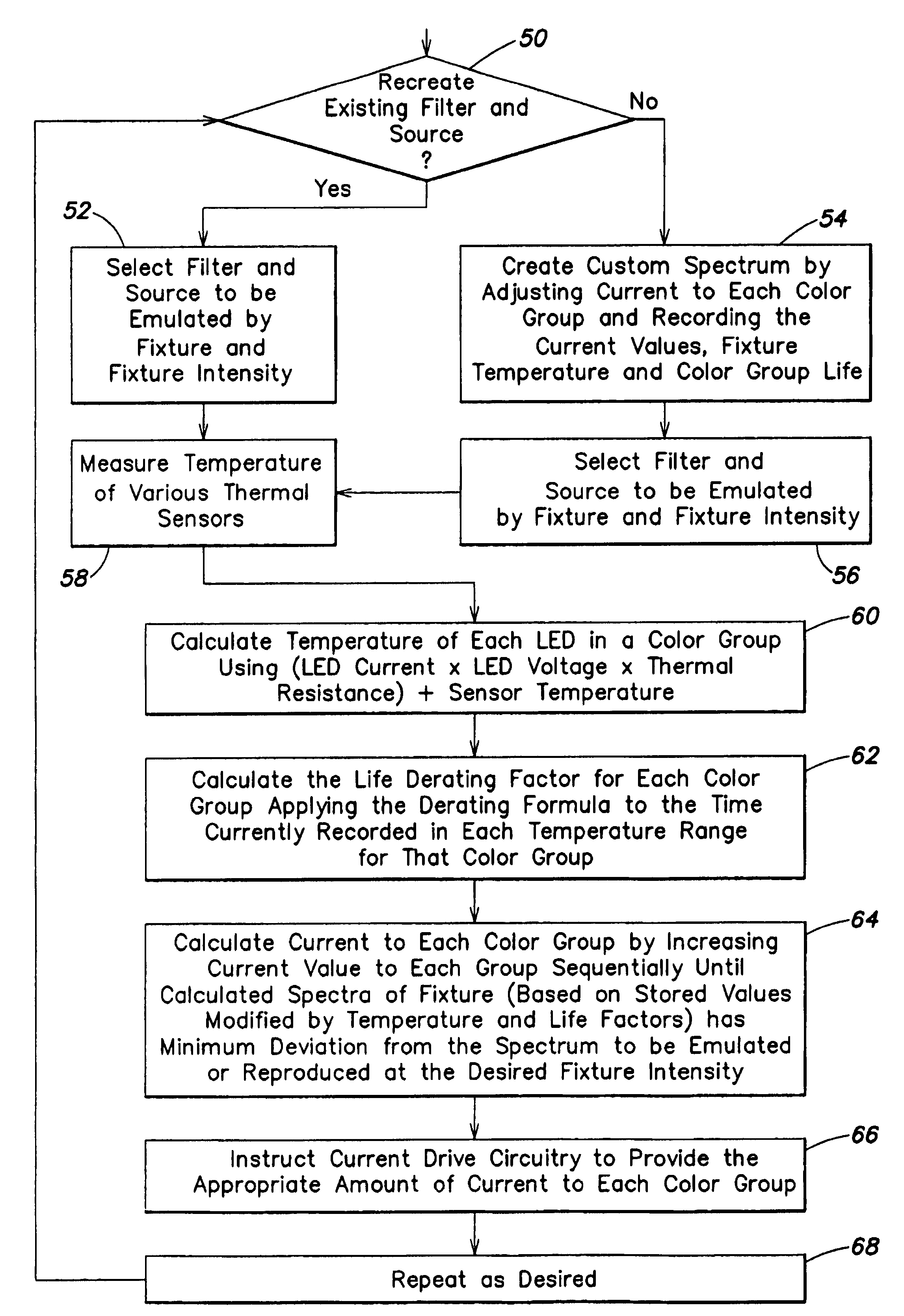
One deficiency of LED lighting fixtures of this kind is that the flux magnitude and the peak flux wavelength can vary substantially from device to device and also can vary substantially with the junction temperature of each device, with LEDs of different colors exhibiting substantially different flux temperature coefficients.
Moreover, the amount of flux produced by each device generally degrades over time, and that degradation occurs at different rates for different devices, depending on their temperatures over time and on their nominal color.
All of these factors can lead to substantial variations in the color spectrum of the composite beam of light projected by such fixtures.
To date, LED lighting fixtures have not been configured to compensate for the identified variations in flux and spectral composition.

Method used


Image

  • Method for controlling the luminous flux spectrum of a lighting fixture
  • Method for controlling the luminous flux spectrum of a lighting fixture
  • Method for controlling the luminous flux spectrum of a lighting fixture

Examples


Embodiment Construction

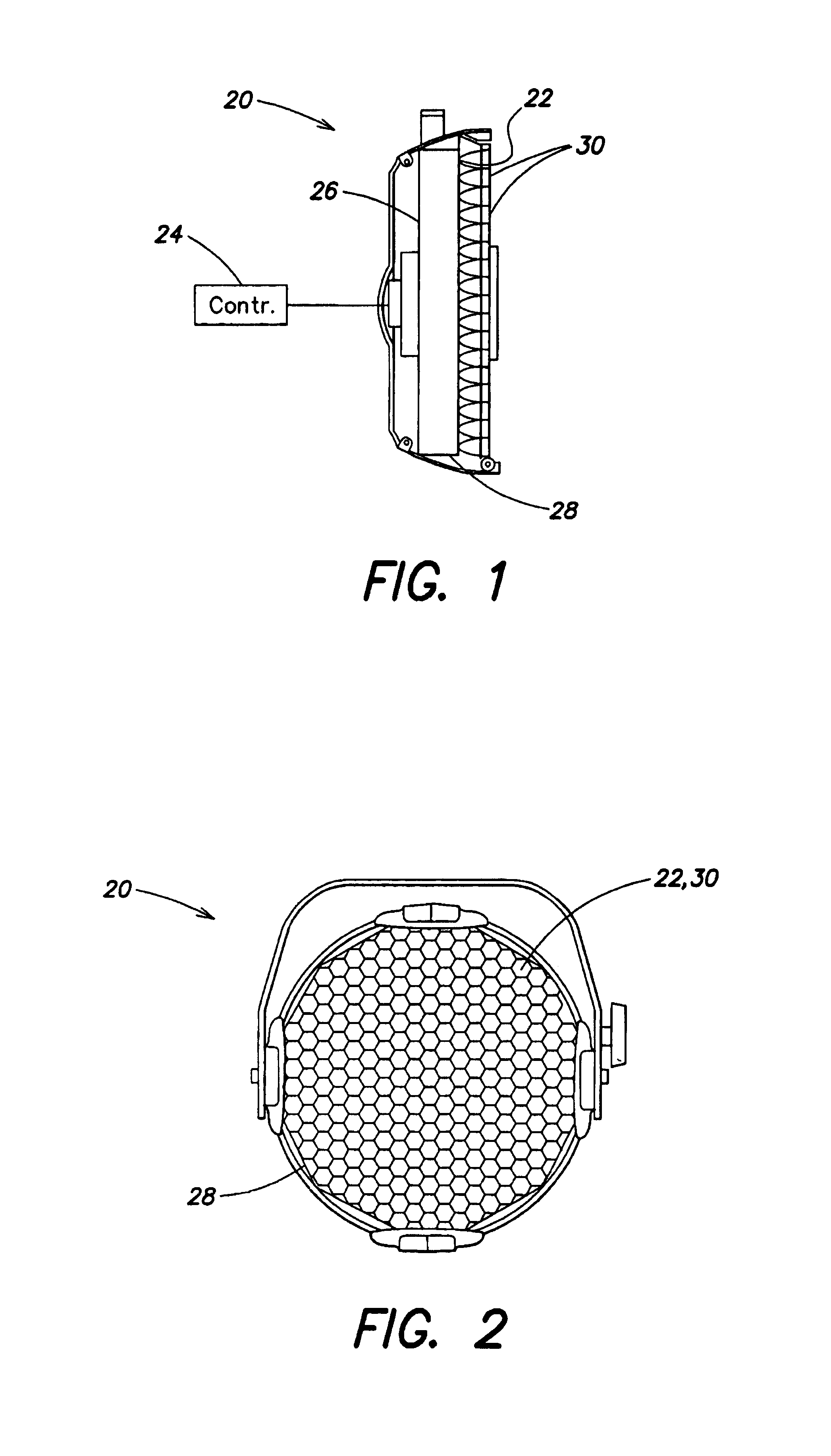
[0030]With reference now to the illustrative drawings, and particularly to FIGS. 1 and 2, there is shown a lighting fixture 20 configured to project a beam of light having a selected luminous flux spectrum. The fixture includes an array of narrowband light emitters, e.g., light-emitting diodes (LEDs) 22, each configured to emit light in a narrowband color. A controller 24 supplies selected amounts of electrical power to the LEDs such that they cooperate to emit light having a prescribed composite luminous flux spectrum. The LEDs are mounted on a heat sink 26 within a housing 28. A collimating lens array 30, located immediately in front of the LED array, includes a separate lens component for each LED, for collecting the emitted light to produce a beam that is projected from the fixture, e.g., toward a theater stage (not shown).

[0031]The LEDs 22 are provided in a number of color groups, each group emitting light having a distinct narrowband color. One preferred fixture embodiment inc...


PUM


Abstract

A method is disclosed for controlling a lighting fixture of a kind having individually colored light sources, e.g., LEDs, that emit light having a distinct luminous flux spectrum that varies in its initial spectral composition, that varies with temperature, and that degrades over time. The method controls such fixture so that it projects light having a predetermined desired flux spectrum despite variations in initial spectral characteristics, despite variations in temperature, and despite flux degradations over time.

Description

BACKGROUND OF THE INVENTION[0001]This invention relates generally to lighting fixtures and, more particularly, to lighting fixtures configured to produce light having a selected color spectrum.[0002]Lighting fixtures of this kind have been used for many years in theater, television, and architectural lighting applications. Typically, each fixture includes an incandescent lamp mounted adjacent to a concave reflector, which reflects light through a lens assembly to project a beam of light toward a theater stage or the like. A color filter can be mounted at the fixture's forward end, for transmitting only selected wavelengths of the light emitted by the lamp, while absorbing and / or reflecting other wavelengths. This provides the projected beam with a particular spectral composition.[0003]The color filters used in these lighting fixtures typically have the form of glass or plastic films, e.g., of polyester or polycarbonate, carrying a dispersed chemical dye. The dyes transmit certain wa...

Claims


Application Information

Patent Timeline
Patent Type & Authority Patents(United States)
IPC IPC(8): G01J3/00H05B37/02H05B44/00
CPCH05B33/0872H05B33/0869H05B45/22H05B45/28
Inventor CUNNINGHAM, DAVID W.
Owner CUNNINGHAM DAVID W
Learn More