
Dual stage suspension with PZT actuators arranged to improve actuation in suspensions of short length

a technology of actuators and suspensions, applied in the field of suspensions, can solve problems such as the approach to other suspension properties such as dynamic characteristics, and affect the actuation of milliactuator systems, and achieve the effect of reducing the impact of secondary actuators on suspension

Inactive Publication Date: 2006-04-04
WESTERN DIGITAL TECH INC
View PDF18 Cites 59 Cited by
  • Summary
  • Abstract
  • Description
  • Claims
  • Application Information

AI Technical Summary

Benefits of technology

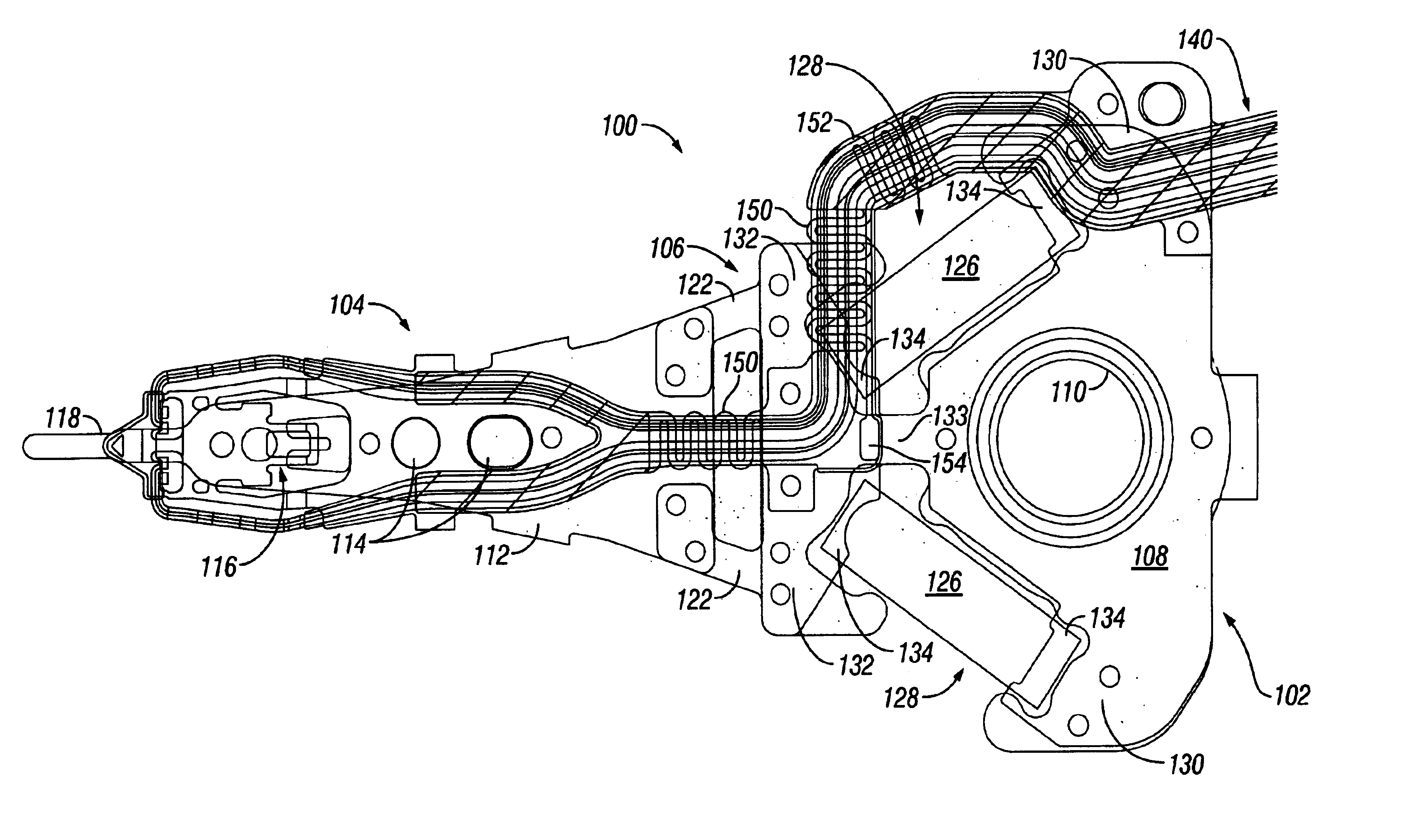
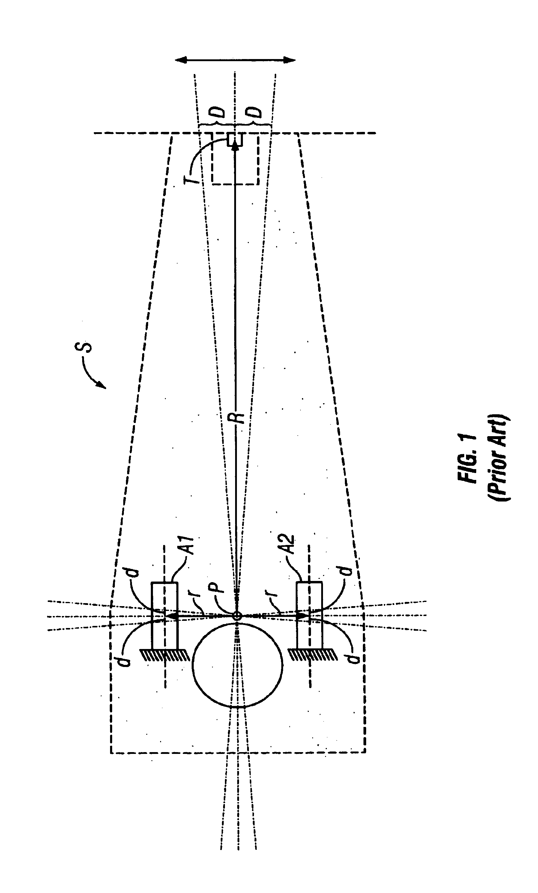
[0011]The foregoing problems are solved and an advance in the art is obtained by an improved dual stage disk drive suspension. The suspension includes a mount plate adapted to mount to a primary actuator, a functional end portion adapted to carry a slider, and a hinge disposed between the mount plate and the functional end portion. A mounting configuration is provided on the mount plate for mounting the suspension to the primary actuator. A pair of secondary actuators are arranged on the suspension in longitudinally overlapping relationship with the mounting configuration so as to minimize the impact of the secondary actuators on suspension length. The secondary actuators are operatively connected to the hinge for producing sway displacement of the slider. They may be either parallel or non-parallel to each other and they may overlap the mounting configuration by any desired amount. The foregoing suspension geometry is ideally suited for suspensions of short length, including suspensions having an overall length of about 10-12.5 millimeters or less.
[0012]In preferred embodiments of the invention, the hinge defines a pair of laterally spaced hinge beams extending between the mount plate and the functional end portion. The mount plate is configured to provide a pair of actuator receiving gaps in which the secondary actuators are situated. Each actuator receiving gap is defined at one end by a static actuator support region of the mount plate and at the other end by a rotational element adapted to rotate in response to stroke displacements of one of the secondary actuators. Each of the rotational elements is operatively connected to one of the hinge beams. Optional stiffener arms may be provided to control and adjust rotational stiffness of the rotational elements. The laterally spaced hinge beams and the optional stiffener arms can be formed from a hinge plate member that is supported in overlapping relationship with the mount plate. The actuator receiving gaps are preferably configured so that the secondary actuators are recessed to provide actuator component protection.
[0013]To provide electrical connections to the slider, the suspension further includes a flexure assembly having electrical lead elements that extend from behind the mount plate (i.e., from the primary actuator) to the slider. To prevent unwanted force imbalances as the hinge is deflected by stroke displacements of the secondary actuators, or by other forces such as air flow or primary actuator seek motion, the electrical lead elements are preferably aligned along a central longitudinal axis of the suspension in the area where they span the hinge. The electrical lead elements are carried on a flexure lead support structure that extends from behind the mount plate to the slider. In areas where the lead support structure is subject to bending as a result of sway displacement of the suspension, the lead support structure may be provided with a bend compliant configuration to reduce resistance to such bending. Similarly, in areas where the lead support structure is subject to axial elongation and contraction as a result of stroke displacement of the secondary actuators, the lead support structure may be provided with an adjustable length configuration to reduce resistance to such axial displacements.

Problems solved by technology

This presents a problem relative to prior art milliactuator systems.
Although some manufacturers have proposed artificial shortening of the suspension's functional end (e.g., load beam) as a solution to this problem, this approach impacts other suspension properties such as dynamic characteristics.

Method used


Image

  • Dual stage suspension with PZT actuators arranged to improve actuation in suspensions of short length
  • Dual stage suspension with PZT actuators arranged to improve actuation in suspensions of short length
  • Dual stage suspension with PZT actuators arranged to improve actuation in suspensions of short length

Examples


embodiment

D. Fourth Exemplary Suspension Embodiment

[0048]Turning now to FIGS. 11 and 12, a suspension 400 is constructed in accordance with a fourth exemplary embodiment of the invention. The suspension 400 is similar in most respects to the suspension 100 described above and corresponding reference numerals (incremented by 300) are used to represent corresponding structure. The suspension 400 has a configuration that is substantially identical to that of the suspension 300. The only difference between the two suspensions is that the mount plate 402 of the suspension 400 is formed with a circular mount plate member 460. A circular mount plate member is easier to manufacture and also is easier to assemble into the suspension assembly 400. In order to utilize a circular shaped mount plate member and be able to protect and align the actuators 426, the load beam component 412 has an extended end portion 464. This extended end portion 464 has a pair of actuator receiving gaps 428 in which the actu...


PUM


Abstract

A suspension for a disk drive includes a mount plate adapted to mount to a primary actuator, a functional end portion adapted to carry a slider, and a hinge disposed between the mount plate and the functional end portion. A mounting configuration is provided on the mount plate for mounting the suspension to the primary actuator. A pair of secondary actuators are mounted in longitudinally overlapping relationship with the mounting configuration so as to minimize the impact of the secondary actuators on suspension length. The secondary actuators are operatively connected to the hinge for producing sway displacement of the slider.

Description

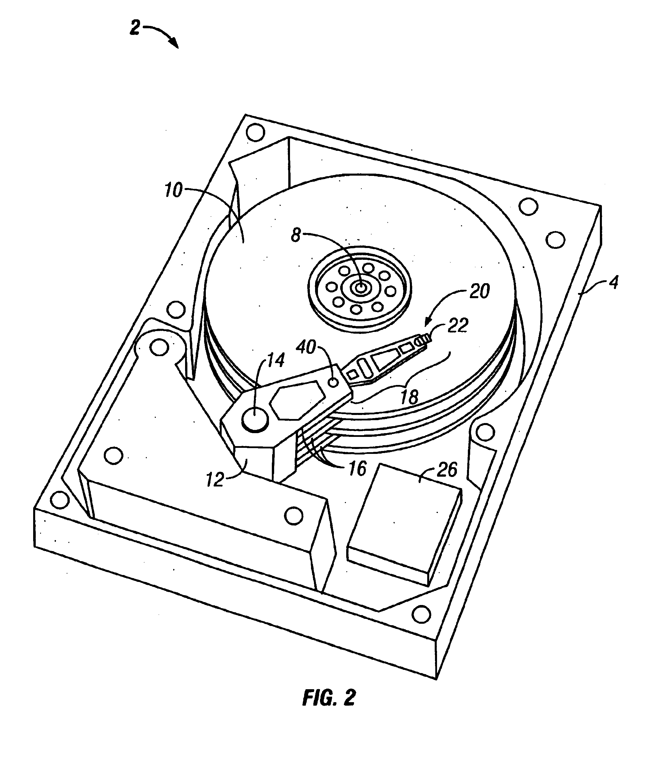
BACKGROUND OF THE INVENTION[0001]1. Field of the Invention[0002]The present invention relates to data storage apparatus for magnetically reading and writing information on data storage media. More particularly, the invention concerns suspensions designed to carry read / write heads in magnetic disk drive storage devices.[0003]2. Description of the Prior Art[0004]By way of background, a read / write transducer in a magnetic disk drive storage device (“disk drive”) is typically incorporated on an air bearing slider that is designed to fly closely above the surface of a spinning magnetic disk medium during drive operation. The slider is mounted to the free end of a suspension that in turn is cantilevered from the arm of a rotary actuator mounted on a stationary pivot shaft. The suspension typically has a mount plate end that attaches to the actuator arm, a bend-compliant hinge connected to the mount plate, and a load beam that extends from the hinge to the free end of the suspension where ...

Claims


Application Information

Patent Timeline
IPC IPC(8): G11B5/56G11B5/596G11B5/48G11B5/55G11B21/10G11B21/21
CPCG11B5/5552G11B5/4853
Inventor SHUM, VICTOR WING CHUN
Owner WESTERN DIGITAL TECH INC
Learn More