Demodulation and synchronization establishment apparatus

a technology of synchronization establishment apparatus and demodulation period, which is applied in the direction of phase-modulated carrier system, synchronisation signal speed/phase control, duplex signal operation, etc., and can solve the problem of reducing the data communication (transmission) rate, the received signal cannot be demodulated correctly, and the reception period is required

Inactive Publication Date: 2006-04-04
KOKUSA ELECTRIC CO LTD
View PDF4 Cites 29 Cited by
  • Summary
  • Abstract
  • Description
  • Claims
  • Application Information

AI Technical Summary

Benefits of technology

[0023]As described above, in accordance with the present invention, synchronization can be established in a short period of time, so even in the above case in which a plurality of received signals containing synchronization establishment signals are received at nearly the same timing, it is possible to establish synchronization with each of the plurality of received signals in a short period of time, and as a result, it is possible to establish synchronizat

Problems solved by technology

However, in the prior-art demodulation circuit shown in FIG. 17, in order to establish clock synchronization based on the preamble pattern, with the performance of a typical receiver, there is a difficulty in that a reception period is required that is as long as approximately 100 symbols from the start of reception of the burst signal.
However, in this case, since the length (period) of the preamble pattern becomes a large fraction of the length (period) of the entire burst slot, there is a problem in that this preamble pattern period becomes wasted time in data communications, thus decreasing the data communications (transmission) rate.
In this case, there is a possibility that the recei

Method used


Image

  • Demodulation and synchronization establishment apparatus
  • Demodulation and synchronization establishment apparatus
  • Demodulation and synchronization establishment apparatus

Examples


Embodiment Construction

[0047]We shall now describe the synchronization establishment circuit (synchronization establishment apparatus) according to Example 1 of the present invention with reference to the drawings. Note that in this Example, we shall also describe the demodulation method according to the present invention.

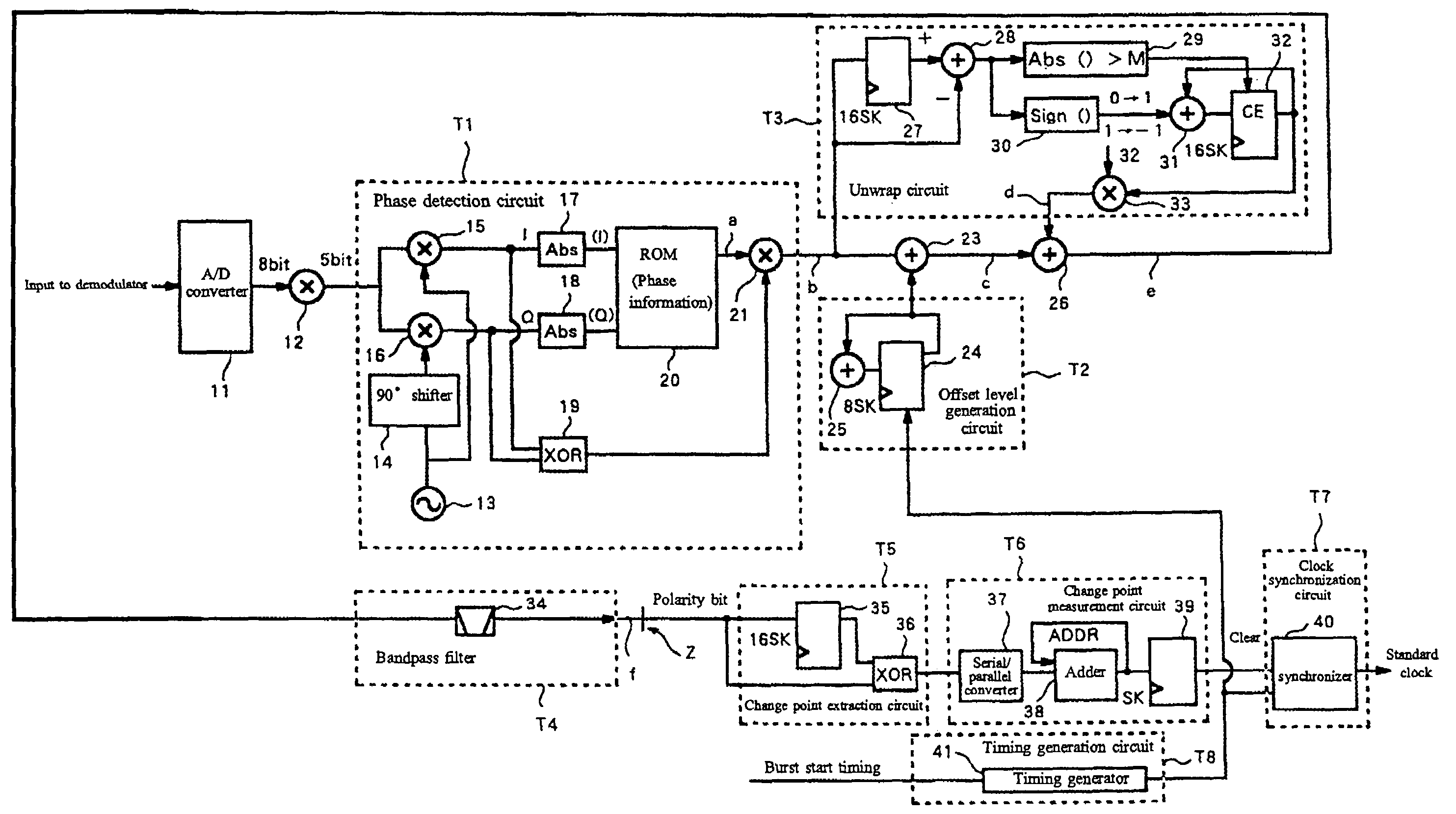
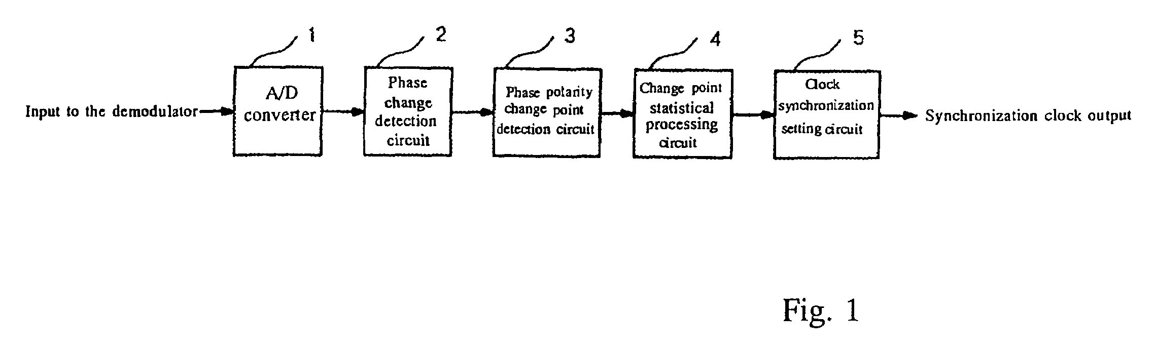
[0048]FIG. 1 is a schematic diagram of an example of the constitution of a synchronization establishment circuit according to this Example. This synchronization establishment circuit is equipped with a wireless receiver that receives burst signals having the same structure as that shown in FIG. 16, and establishes the clock synchronization based on the preamble pattern that is contained in the burst signals.

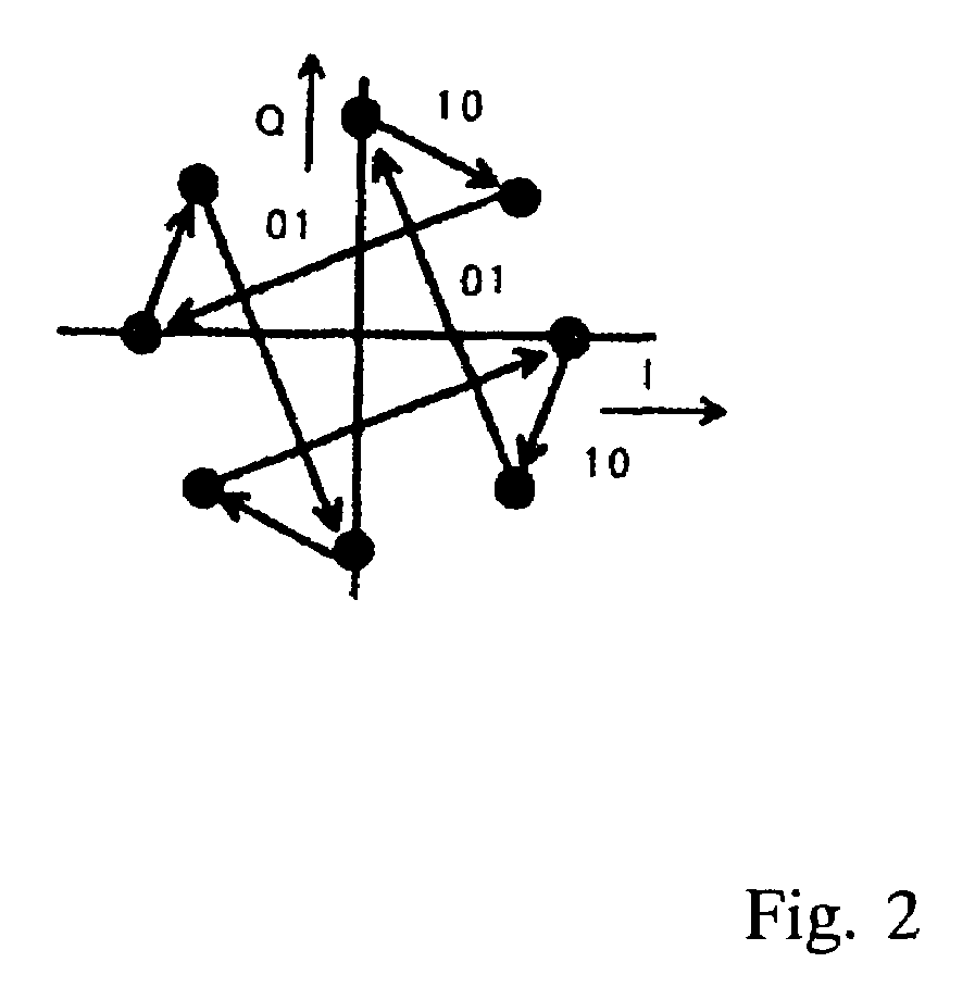
[0049]In addition, this Example illustrates the case wherein the wireless transmitter and the wireless receiver perform the wireless communication of signals by using the π / 4-shift QPSK modulation scheme. In addition, this Example illustrates the case in which the preamble pattern tha...


PUM


Abstract

A demodulation method for establishing clock synchronization within a short period of time from a received signal modulated by π/4-shift QPSK modulation that contains a synchronization establishment signal wherein the change in phase periodically alternates between positive and negative, and for demodulating the received signal. The method includes establishing synchronization from the received signal based on the timing of changes in the positive/negative polarity of the change in phase of the synchronization establishment signal contained in the received signal, and demodulating the received signal.

Description

BACKGROUND OF THE INVENTION[0001]1. Field of the Invention[0002]The present invention relates to a demodulation method wherein clock synchronization is established from a burst signal which is modulated by means of the π / 4-shift QPSK (Quadrature Phase Shift Keying) modulation scheme, for example, to a synchronization establishment apparatus, modem or base station, and particularly to a technique for establishing synchronization in a short period of time.[0003]2. Description of the Prior Art[0004]In a wireless communications system wherein wireless communication is performed in a burst manner, a wireless transmitter wirelessly transmits a burst signal which is modulated by a modulator, and at the time that a wireless receiver begins the receipt of the burst signal, the establishment of clock synchronization from the burst signal is performed by a demodulator In addition, in such a wireless communications system, various modulation schemes and demodulation schemes are used, for exampl...

Claims


Application Information

Patent Timeline
IPC IPC(8): H04L7/00H04L7/06H04L27/22H04B7/26H04L7/027H04L7/04H04L7/10H04L27/233
CPCH04L27/2332H04L7/027H04L7/046
Inventor NAKAMURA, MANABUMIYASHITA, SHINICHI
Owner KOKUSA ELECTRIC CO LTD
Why Eureka
Try Eureka