System for motion control, method of using the system for motion control, and computer-readable instructions for use with the system for motion control

a technology of motion control and motion control, applied in the direction of frequency-division multiplex, electric programme control, program control, etc., can solve the problems of increasing complexity, speed and precision demands, and the control of moving components in modern manufacturing equipment, such as the equipment used to process and package semiconductor devices, to reduce the need for wiring

Inactive Publication Date: 2006-04-04
MOTION ENG
View PDF20 Cites 49 Cited by
  • Summary
  • Abstract
  • Description
  • Claims
  • Application Information

AI Technical Summary

Benefits of technology

[0022]Accordingly, it is an object of this invention to provide a system for motion control, a method of using a system for motion control, and a computer readable medium storing instructions for operating a system for motion control that provides a motion control system with a reduced need for wiring while retaining centralized control of the motion system.

Problems solved by technology

The control of moving components in modern manufacturing equipment, such as the equipment used to process and package semiconductor devices, has become extremely complex as demands for both speed and precision increase.
Such complexity is seen, for example, in the implementation of feedback control loops used in servo motion control systems.
Due to various mechanical and electrical sources of error (such as, e.g., noise, backlash, part flexing), a difference between the desired motion profile and the actual motion profile is often present.
Although multi-media networks guarantee the average streaming rate, they do not provide strict periodicity, as the data is buffered at both ends in multi-media appliances and can therefore tolerate deviations in the delivery period.
Thus, multi-media networks are not ideal for real-time motion control networks.
However, there are limitations to using ARCNET.
The first limitation is a moderate bit rate (10 Mbit / s) that is not fast enough to send out torque / current demands.
Moreover, the speed of ARCNET cannot be upgraded to 100 Mbit / s over copper without a fundamental re-design.
ARCNET can use twisted pair copper but has no scrambling and therefore data transmission may potentially cause electromagnetic interference.
Nor can it report where such a fault has occurred, thereby impeding automatic and remote fault diagnosis.
ARCNET has no mechanism for auto-enumeration, which increases the time necessary to commission a machine.
ARCNET uses a token-passing scheme; such schemes are inherently less robust in the event of electromagnetic interference than time-division multiplexing as the loss of the token requires the network to re-start a configuration process wherein the token is re-created.
ARCNET has no propagation time correction mechanism and therefore would suffer significant data skew if a moderate number of nodes is used with a short cycle time.
Therefore, the position of a node within the network cannot be reliably used to signify the axis of control since this position would change if another node were disconnected during operation.
Proposed 1394 has no time-correction mechanism for dealing with the situation where a synchronization message is received at different times at different points in the network, and therefore would suffer significant data skew if a moderate number of nodes were used with a short cycle time.
Ethernet also cannot be operated as a full-duplex ring and therefore has no means of operating all nodes after a link has been severed.
Ethernet lacks an appropriate mechanism for auto-enumeration since it cannot assign node numbers on the basis of position.
Ethernet is normally half-duplex; full-duplex operation introduces the expense, complexity, and temporal uncertainty of using switches.
While this network is accepted for use in certain industry sectors such as machine tools and automotive assembly lines, it has several significant limitations.
SERCOS networks thus limit the feasibility of close inter-axis coupling (including centralized implementation of electronic gearboxes and cams) and on-the fly changes of trajectory.
SERCOS does not work with a copper transmission medium, which significantly increases the cost and poses a problem in applications where the network medium must be routed through flexible trunking such as cable retractors.
This is due to the fact that the long term flexure characteristics of fiber are poor.
MACRO cannot operate in a tree topology or in the event of a fault and lacks node discovery and auto-enumeration capabilities.
It is unclear whether MACRO has a time-correction mechanism and therefore may suffer significant data skew if an even moderate number of nodes were used with a short cycle time.

Method used


Image

  • System for motion control, method of using the system for motion control, and computer-readable instructions for use with the system for motion control
  • System for motion control, method of using the system for motion control, and computer-readable instructions for use with the system for motion control
  • System for motion control, method of using the system for motion control, and computer-readable instructions for use with the system for motion control

Examples


first embodiment

[0106]In a first embodiment, the master transmits two different correction factors to each slave related to the time taken for a telegram sent from the master to reach the slave in the forward direction and in the reverse direction around the ring. These quantities are called the forward and reverse path time correction or FPTC and RPTC, and their transmission can be performed, e.g., using a MCT during the discovery phase 60.

[0107]During the operational phase 62, a MST is transmitted from the master 36 on a periodic basis. The MST is the synchronization signal for the operation of the motion control nodes on the network and, among other functions, the MST helps synchronize the acquisition of position data for each servo loop. Each node can phaselock an internal timer to the MST synchronization signal.

[0108]In one embodiment for operation with a complete network ring topology, since the MST is a continuously running master synchronization signal, each slave node can use its own FPTC ...

second embodiment

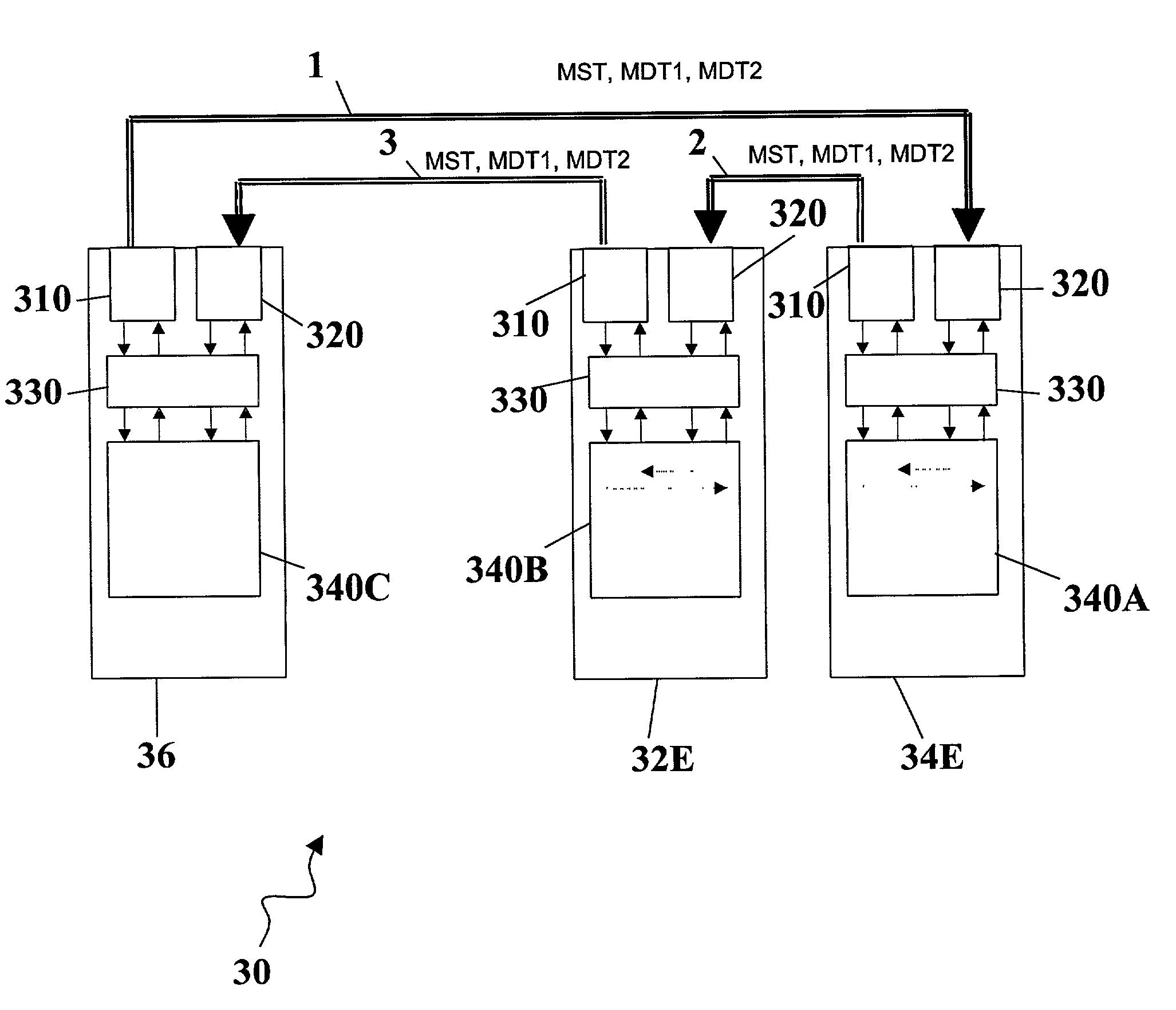
[0109]A second embodiment for operation in the event of a network fault condition, the MST will be transmitted from both the P0 and the Q port of the master36. In this case, unless the faulty link is immediately adjacent to the master 36, at least one slave node 36 will receive the MST at its P0 port rather than its Q port. As illustrated in FIG. 25, in the case of a break between Slave 32E and Slave 34E, the MST that is sent in the reverse direction is received by slaves 39E, 38E, and 34E. Thus, the FPTC is no longer appropriate for slaves 39E, 38E, and 34E, and those slaves must instead use the RPTC.

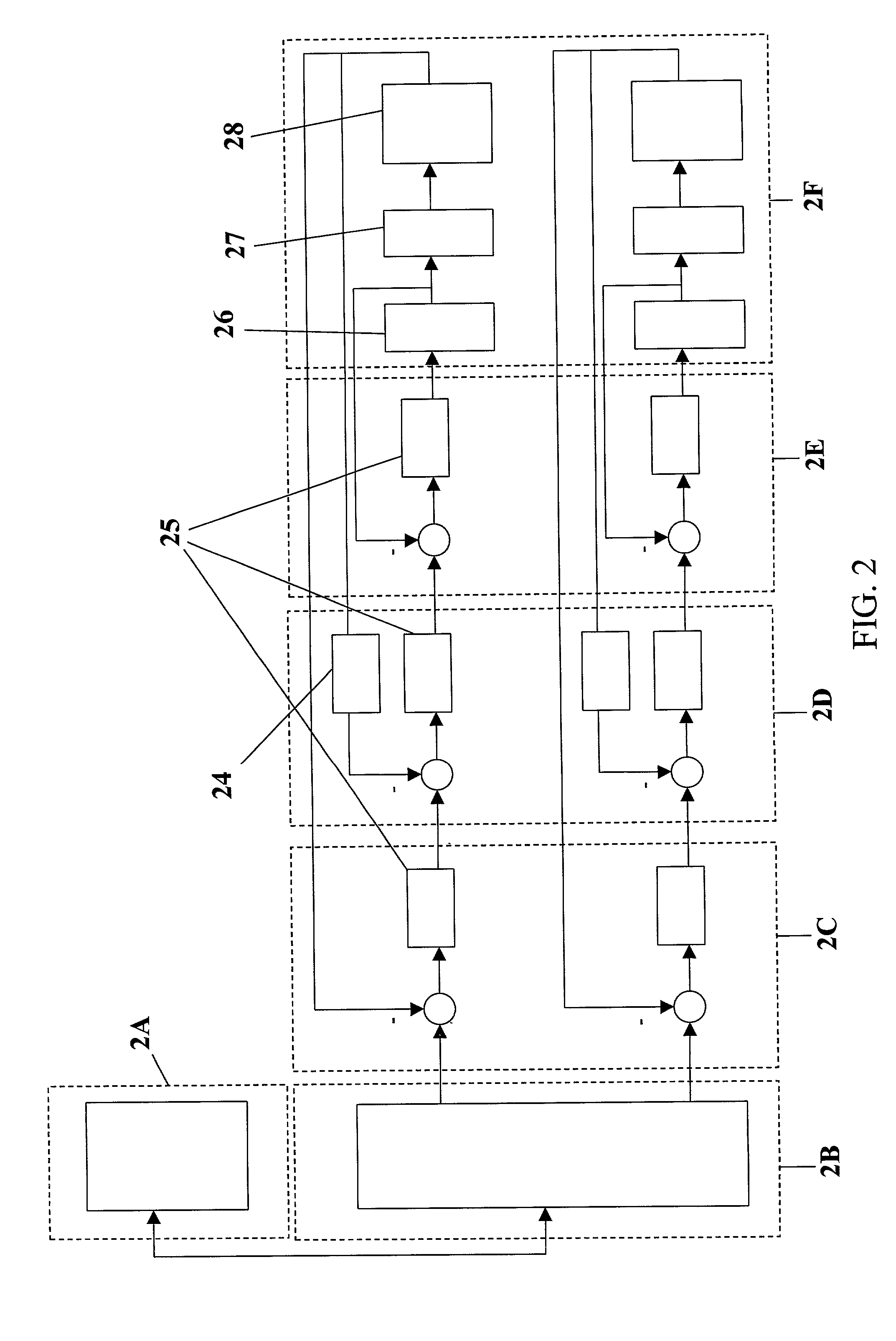
[0110]The benefit derived from the timing correction can be shown in the context of one embodiment of the invention illustrated in FIG. 26. The network controller (master 36) contains the motion planning function, a digital processor, which typically implements the position loop, as well as other filtering and control functions. The network nodes (slaves 32E and 34E) contain the motor ...


PUM


Abstract

A motion control system and method that includes a central controller configured to generate first and second demand control signals to be used to define actuation motion of respective first and second actuators. The central controller is in communication with first and second nodes by way of a data network, each node including at least a respective actuator configured to implement at an actuator time a motion or force-related effort based upon the respective demand control signal. Each node also includes a memory configured to store at least one respective propagation delay parameter related to a signal propagation delay between the central controller and the node. A timing mechanism establishes timing at each node based on the respective propagation delay parameter so that the actuator time at the nodes occurs simultaneously. Strictly cyclic and / or full-duplex high-speed communication can be supported. The network can be wired in a ring or as a tree and with twisted pair cabling or fiber. The central controller issues demand signals to the nodes that are actuator, servo motor drive, and / or I / O devices. The central controller can also provide a timing message that is used by the nodes, in conjunction with local delay correction circuitry, so that the simultaneous acquisition of data and the simultaneous implementation of controlled action occur.

Description

BACKGROUND OF THE INVENTION[0001]1. Field of the Invention[0002]This invention relates to the control of motion of complex machines, and specifically to an improved system, method, and computer-readable instructions designed to minimize wiring yet retain the flexibility of centralized control systems.[0003]2. Discussion of the Background[0004]The control of moving components in modern manufacturing equipment, such as the equipment used to process and package semiconductor devices, has become extremely complex as demands for both speed and precision increase. Such complexity is seen, for example, in the implementation of feedback control loops used in servo motion control systems. These servo control systems are used for critical positioning actuators, typically referred to as motion axes, in a complex machine.[0005]A schematic representation of an exemplary basic servo axis motion control system 10 is shown in FIG. 1. Typically, a desired motion path profile is generated at a motion...

Claims


Application Information

Patent Timeline
Patent Type & Authority Patents(United States)
IPC IPC(8): G05B11/00G05B15/02G01C22/00G05BG06F13/10H04J3/06H04J99/00H04L12/28H04L12/42H04L12/423
CPCH04J3/0682H04L12/417H04L12/422H04L12/423H04L12/4035H04J3/062H04J3/0638H04L7/08H04L2012/4026G05B15/02G05B11/01
Inventor PEARCE, ROBERTCLINE, DAVID
Owner MOTION ENG
Why Eureka
Try Eureka