
Aircraft panel

Inactive Publication Date: 2006-04-11
SAAB AB
View PDF19 Cites 68 Cited by
  • Summary
  • Abstract
  • Description
  • Claims
  • Application Information

AI Technical Summary

Benefits of technology

[0014]The inventive embodiments are arranged to give the fuselage vessel the required stiffness and the sufficient amount of material to sustain all aircraft loading both from static and from fatigue point of view and to support and provide fixing points for frames within the aircraft fuselage.
[0015]A major advantage with the inventive concept is that stringer manufacturing and installation costs can be avoided. Furthermore, the frames for the new skin panel do not need any weakening cut-outs for the stringers. The new panel will attain the same or lower weight than present design solutions.

Problems solved by technology

Aircraft, whether military or civil, are subjected to a high degree of stress and need to comply with stated aircraft regulations.
Considerable disadvantages exist however in the present design which requires installation of the stringers and frames.
Manufacturing of stringers with different geometry is very expensive.
Another disadvantage is that stringer installation by riveting is time-consuming and expensive.
The method causes a great number of holes through the outer skin, which always increases the potential for corrosion and fatigue problems.
In the Saab 340 and Saab 2000 project, the frames have cut-outs for the stringers, which decreases the stiffness of the frames.
A problem with this solution is that it increases the complexity in the.
Other techniques for stringer installation may reduce some of these disadvantages but are still time-consuming and difficult.
However, there are some major concerns regarding the use of composites in cabin structures that remains to be solved.
The epoxy resins, that are used for structural applications, do not meet the Fire, Toxicity and Smoke (FTS) requirements.
Furthermore, the crash worthiness requirements are very difficult to meet due to the composites high degree of brittleness.
A problem with known lightweight designs is that they have proven to be more sensitive to damage and more difficult to repair and maintain.
Both these qualities provide for reluctance among the aircraft operators to adopt the new design solutions.
This will probably cause more structural break-up and thereby less protection for the passengers unless new composite designs will emerge.

Method used


Image

  • Aircraft panel
  • Aircraft panel
  • Aircraft panel

Examples


Embodiment Construction

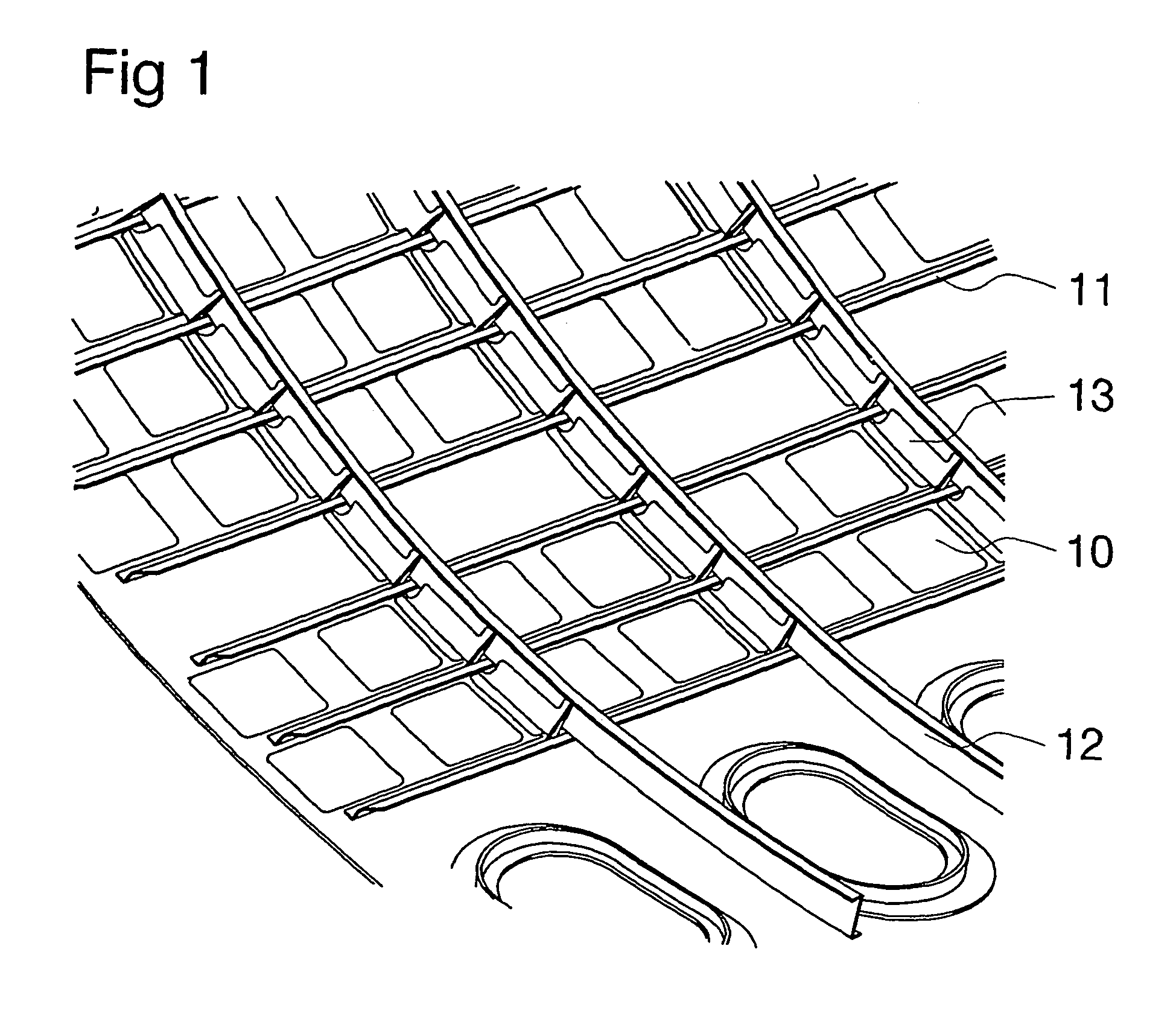
[0020]Referring to FIG. 1, there is shown a traditional fuselage skin panel reinforced with circumferential frames 12 and longitudinal stringers 11. Clips 13 are used between each stringer 11 to connect each frame 12 to the outer skin 10. The clips 13 are riveted to the skin 10 and to the frame 12, which is a very expensive and time-consuming attachment.

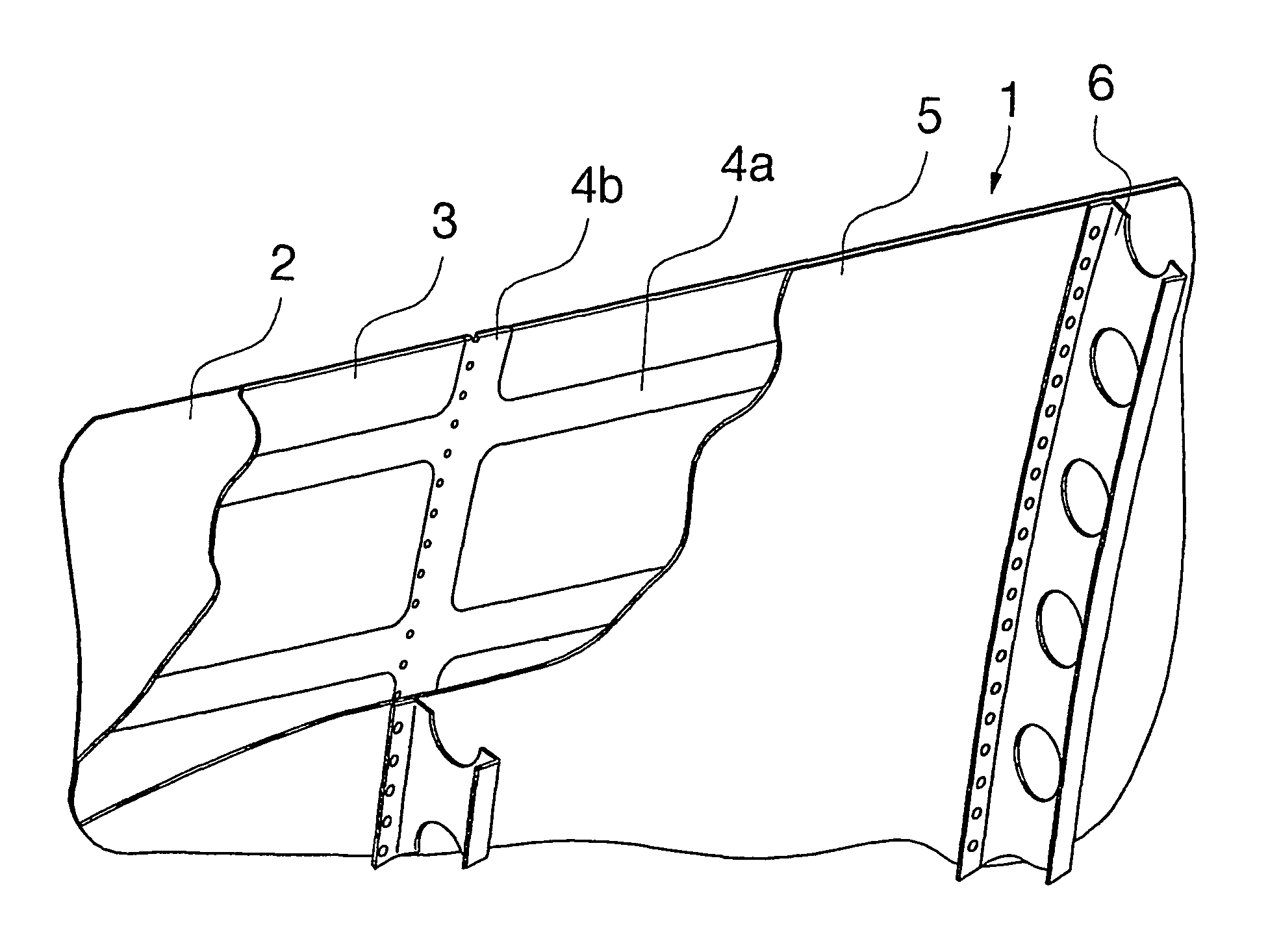
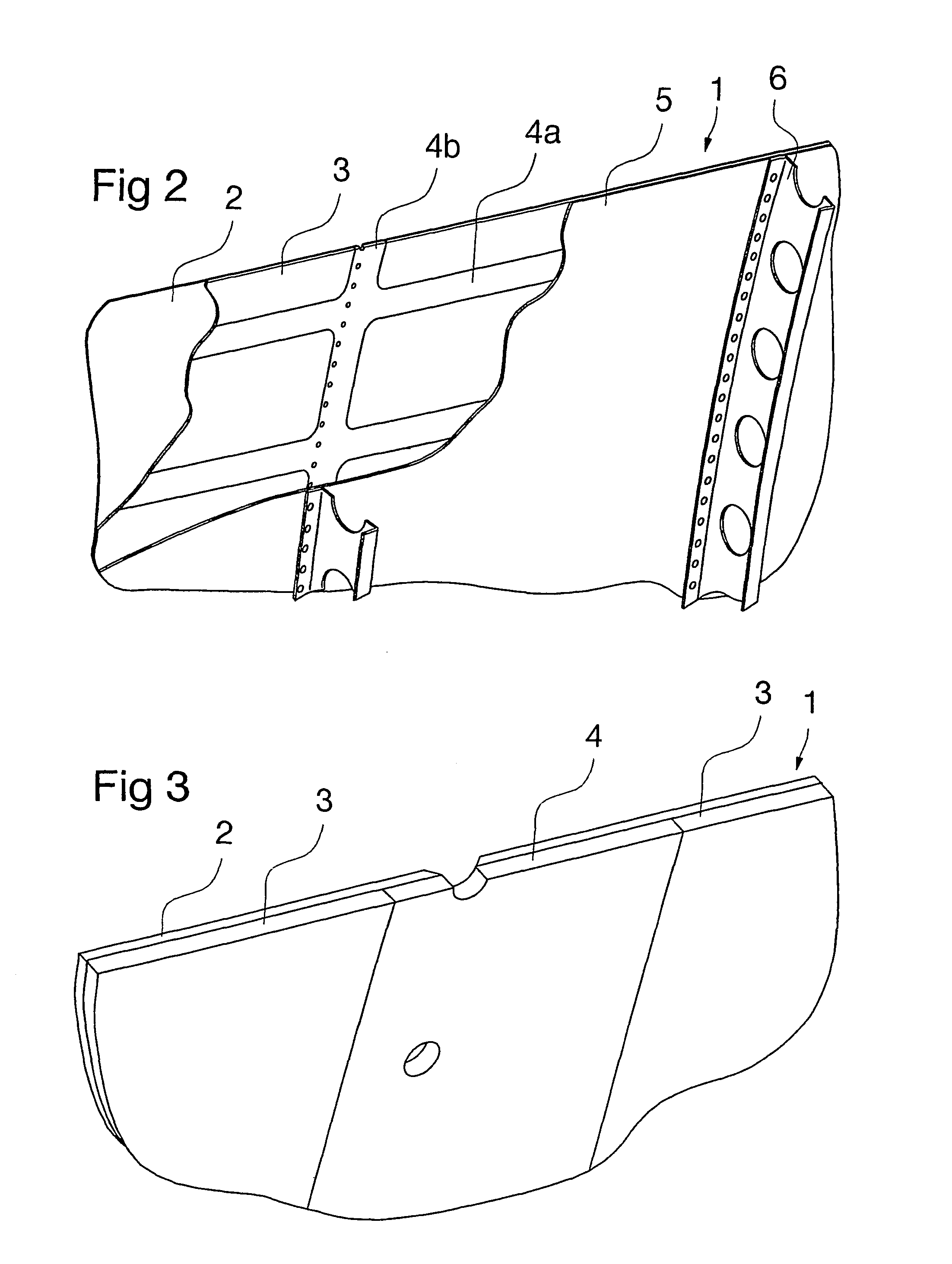
[0021]Referring to FIG. 2 there is shown an aircraft panel 1 comprising a sandwich construction with an outer skin portion 2 of high strength material, an inner skin portion 5 of high strength material and an intermediate core material. The outer skin portion and inner skin portion are preferably both made of aluminum, which is well suited for this purpose both from a cost and crash worthiness aspect. Embodiments where a different high strength material is used for one or both skin portions are also possible. The core material comprises a distance material that makes the panel act as a damage tolerant sandwich construction. This dist...


PUM

PropertyMeasurementUnit
Densityaaaaaaaaaa
Strengthaaaaaaaaaa

Abstract

An aircraft panel comprising a sandwich construction with an outer skin portion of high strength material, an inner portion of high strength material and an intermediate core material. The core material includes areas with low density core material and a reinforcement grid of high strength material, with longitudinal and transversal grid members.

Description

BACKGROUND OF THE INVENTION[0001]The present invention relates to an aircraft panel and in particular to an aircraft fuselage skin panel comprising a sandwich construction with an outer skin portion of high strength material, an inner skin portion of high strength material and an intermediate core material.[0002]Aircraft, whether military or civil, are subjected to a high degree of stress and need to comply with stated aircraft regulations. Nevertheless, their manufacture must not involve excessive cost. These somewhat contradictory criteria apply in particular to the manufacture of curved skin panels used for fuselage, wings and other part of the aircraft where lightweight materials and simple manufacturing methods are important to keep the cost on an acceptable level.[0003]Today skin panel surfaces on a modern aircraft are supported by one or more of the following methods:[0004]frames[0005]stringers[0006]honeycomb sandwich[0007]Traditional fuselage skin panels are reinforced with ...

Claims


Application Information

Patent Timeline
IPC IPC(8): B64C1/06B32B5/18B32B15/20B64C1/12
CPCB32B5/18B64C1/12B32B15/20B32B2307/304B32B15/08B32B2250/03B32B2605/18B32B2307/56B32B15/046B32B2311/24
Inventor FOLKESSON, MATSTHURESSON, STEFAN
Owner SAAB AB
Learn More