Ultrasonic apparatus with non-rotating horn and rotating anvil for welding plastic parts

a technology which is applied in the field of ultrasonic equipment and plastic parts welding using ultrasonic wave energy, can solve problems such as wrinkles and/or jams, and achieve the effect of preventing the deflection of the horn

Inactive Publication Date: 2006-04-11
ILLINOIS TOOL WORKS INC
View PDF23 Cites 28 Cited by
  • Summary
  • Abstract
  • Description
  • Claims
  • Application Information

AI Technical Summary

Benefits of technology

[0007]The invention is directed to a method and an apparatus for producing zippered bags at high speeds. The zipper comprises a pair of zipper strips that are welded at spaced intervals along the zipper during the automated production process. The zipper strips may be either flanged or flangeless. An ultrasonic welding station is disclosed comprising a non-rotating horn and a rotary anvil that cooperate to weld the zipper strips together at spaced intervals. The horn is substantially rigidly coupled to the end of a piston rod of an air cylinder. The air inside the cylinder cushions the deflection of the horn away from the anvil as the anvil rotates into a position where a plateau opposes a distal end of the horn. It is expected that this cushioning effect will alleviate the possibility of the zipper profiles being forced or deflected from a straight line, which could cause the creation of wrinkles and / or jams.

Problems solved by technology

It is expected that this cushioning effect will alleviate the possibility of the zipper profiles being forced or deflected from a straight line, which could cause the creation of wrinkles and / or jams.

Method used


Image

  • Ultrasonic apparatus with non-rotating horn and rotating anvil for welding plastic parts
  • Ultrasonic apparatus with non-rotating horn and rotating anvil for welding plastic parts
  • Ultrasonic apparatus with non-rotating horn and rotating anvil for welding plastic parts

Examples


Embodiment Construction

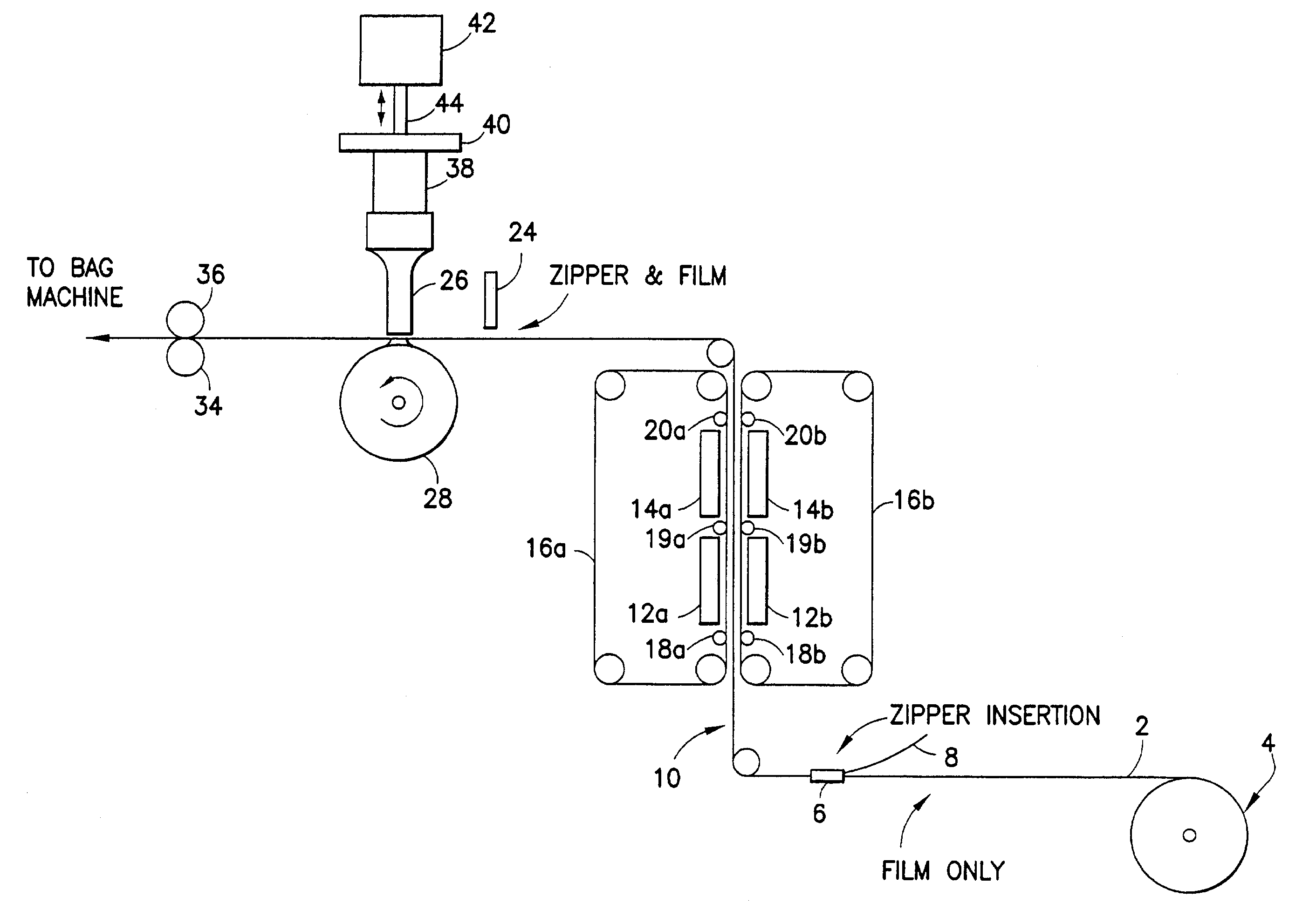
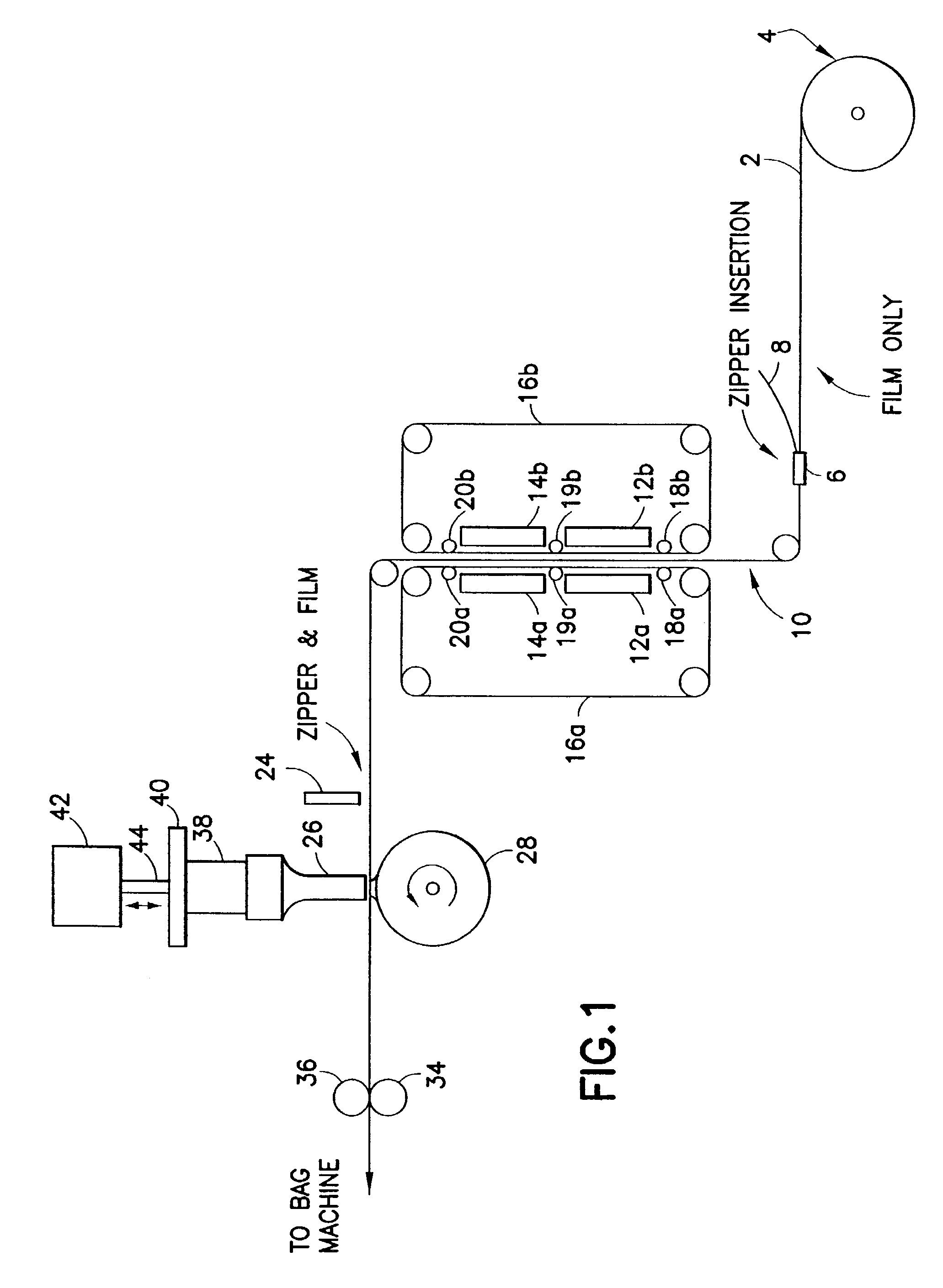
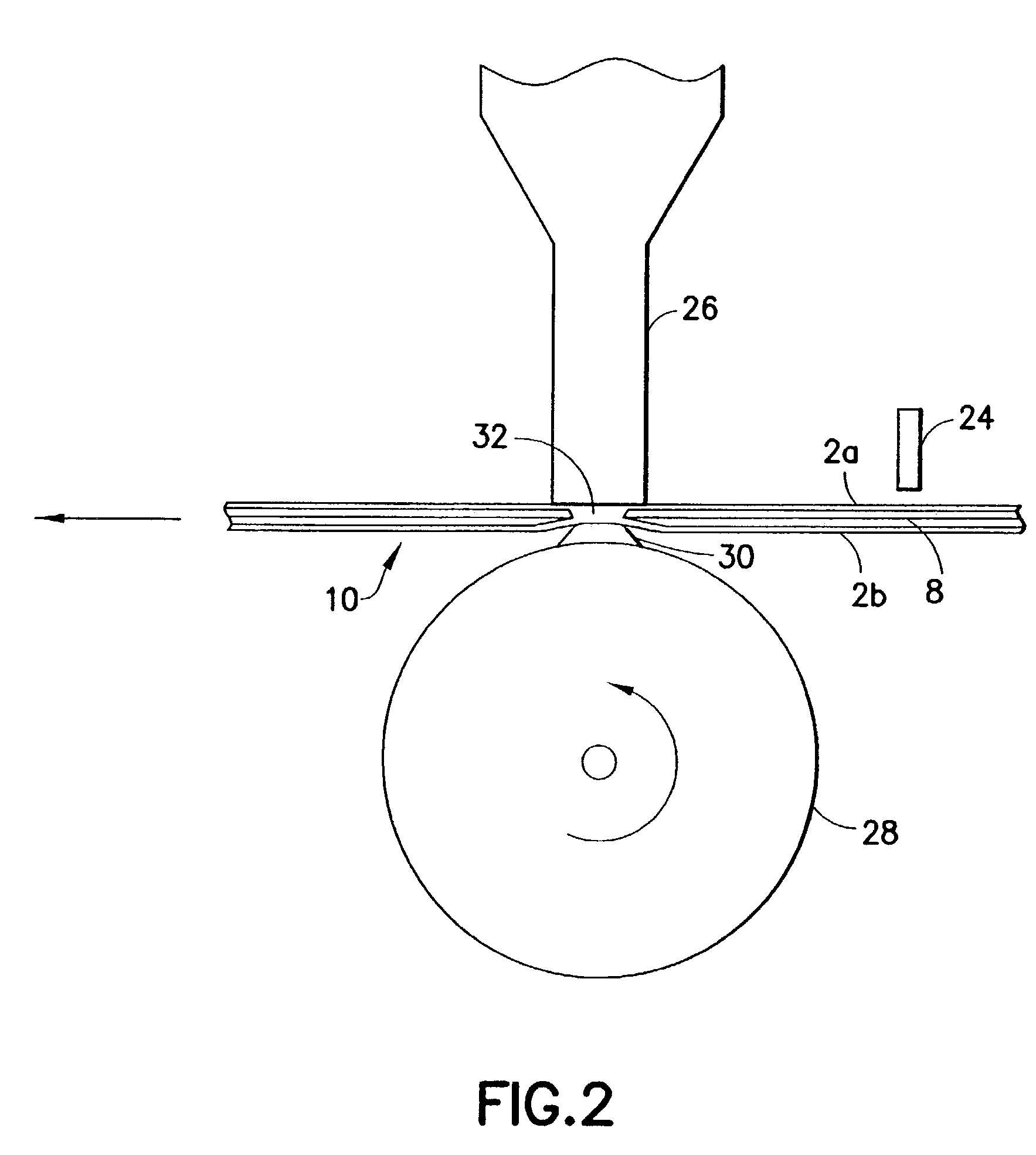
[0018]A method and an apparatus in accordance with one embodiment of the present invention will now be described with reference to FIGS. 1–3. FIG. 1 shows a zipper-to-film sealing apparatus and an ultrasonic welding apparatus that work in conjunction with a bag making machine. In particular, the sealing apparatus disclosed herein can be used in conjunction with a pre-made bag machine, i.e., a machine that makes bags but does not fill them. In this embodiment, the zipper and film move continuously outside the bag machine, but move intermittently inside the bag machine in a well-known manner. However, it should be appreciated at the outset that the present invention is not limited to use with continuously moving zipper and film, but may also be used to stomp zipper that moves intermittently. In the latter case, the ultrasonic welding apparatus can be moved from a station upstream from the dancer assembly (i.e., outside the bag machine) to a position downstream from the dancer assembly...


PUM

PropertyMeasurementUnit
linear speedaaaaaaaaaa
tangential velocityaaaaaaaaaa
ultrasonic wave energyaaaaaaaaaa

Abstract

A method and an apparatus for ultrasonically welding plastic parts together. The ultrasonic welding apparatus includes: an air cylinder having a piston rod; an ultrasonic horn substantially rigidly coupled to an end of the piston rod and having a distal end; a rotary anvil having an axis of rotation generally perpendicular to an axis of the piston rod and comprising a periphery; a transducer for converting electric potential differences into ultrasound wave energy, the horn being acoustically coupled to the transducer; and drive means for causing the anvil to rotate. The distal end of the horn confronts the periphery of the anvil throughout rotation of the anvil. On one application, interlocked zipper strips are passed through a gap between the distal end of the horn and the periphery of the anvil. The anvil periphery has a plateau that presses the zipper against the distal end of the horn. The transducer is energized in synchronism with the plateau being opposed to the distal end of the horn.

Description

BACKGROUND OF THE INVENTION[0001]This invention generally relates to methods and apparatus for welding plastic parts using ultrasonic wave energy. In particular, the invention relates to methods and apparatus for pre-sealing or stomping two interlocked zipper strips at spaced intervals along the zipper.[0002]Reclosable bags are finding ever-growing acceptance as primary packaging, particularly as packaging for foodstuffs such as cereal, fresh vegetables, snacks and the like. Such bags provide the consumer with the ability to readily store, in a closed, if not sealed, package any unused portion of the packaged product even after the package is initially opened.[0003]Reclosable plastic zipper assemblies are useful for sealing thermoplastic pouches or bags. Typically, the plastic zippers include a pair of interlockable profiled members that form a closure. The profiles in plastic zippers can take on various configurations, e.g. interlocking rib and groove elements having so-called male...

Claims


Application Information

Patent Timeline
Patent Type & Authority Patents(United States)
IPC IPC(8): B29C65/08B29C65/00B29C65/18B31B19/90
CPCB29C65/086B29C66/80B29C66/81611B29C66/83423B29C66/83511B29C66/932B29C66/93451B29C66/98B31B19/90B29C65/7891B29C66/474B29C66/4322B29C66/961B29C66/81427B29C66/944B29C66/00441B29C66/1122B29C66/322B29C66/43B29C66/83411B29C66/8746B29C2793/009B29L2005/00B31B2219/9019B29C65/18B29C65/00B29C66/934B29C66/73921B29C66/8122B29C66/8242B31B70/8132B29K2827/18
Inventor OWEN, KEVIN
Owner ILLINOIS TOOL WORKS INC
Why Eureka
Try Eureka