Supercharge Your Innovation With Domain-Expert AI Agents!

Color image processing apparatus and color image processing method

a color image processing and color image technology, applied in the field of color image processing apparatus and color image processing method, can solve the problems of color chip determination, black ink color matching, and inability to fix the desired amount of color material on the sheet of printing material, etc., to achieve smooth color reproducibility, easy interpolation, and quick color determination

Inactive Publication Date: 2006-04-11
FUJITSU LTD
View PDF11 Cites 0 Cited by
  • Summary
  • Abstract
  • Description
  • Claims
  • Application Information

AI Technical Summary

Benefits of technology

The present invention provides a color image processing apparatus and method that uses a parameter selection to find a parameter that minimizes the difference between the input and output color spaces, resulting in a smooth color reproduction with minimal unnatural jump or unmatched color blending. This allows for the creation of high-quality color images. Additionally, the invention allows for the adjustment of the number of color signals and parameters based on the user's needs, and the use of a parameter table to save time and ensure smooth color reproduction.

Problems solved by technology

In such an image forming apparatus, it is desired to reduce the amount of color materials used in color printing as much as possible, since the color material is generally expensive.
Further, there is a problem that when a color image is formed, a desired amount of color material cannot be fixed on a sheet of printing material due to the property of the medium or color material (ink, toner or the like).
Therefore, it becomes difficult to take a good matching between the three color inks (CMY) and the black ink.
Further, a light portion of the image is also added with a considerable amount of black component, the background texture of the image at the portion tends to be dirty due to the black component.
However, according to the general method of the conventional UCR method, since a part of the CMY color components are replaced with the K-separation, the color reproducibility is greatly deteriorated.
Also, there is also a problem that the deepness of the color image cannot be completely reproduced after the UCR processing.
Therefore, it is difficult to improve the color reproducibility of an image after undergoing the UCR processing.
That is, it is difficult to determine a parameter which can provide good balance for every color.
Therefore, when a color is actually outputted from the printing device or the like, for example, if it is requested to produce a gradation from a monochrome tone to a primary color (i.e., a color represented by only one color component of CMY components) or to produce a gradation from the monochrome tone to a secondary color (i.e., a color represented by two color components of the CMY components), the UCR rate does not vary uniformly in response to the input color signal.
Therefore, since this method does not cope with the difference in lightness of hue of the image, it is difficult to create a color image with a quality desired by the user.

Method used


Image

  • Color image processing apparatus and color image processing method
  • Color image processing apparatus and color image processing method
  • Color image processing apparatus and color image processing method

Examples


second embodiment

(B) DESCRIPTION OF SECOND EMBODIMENT

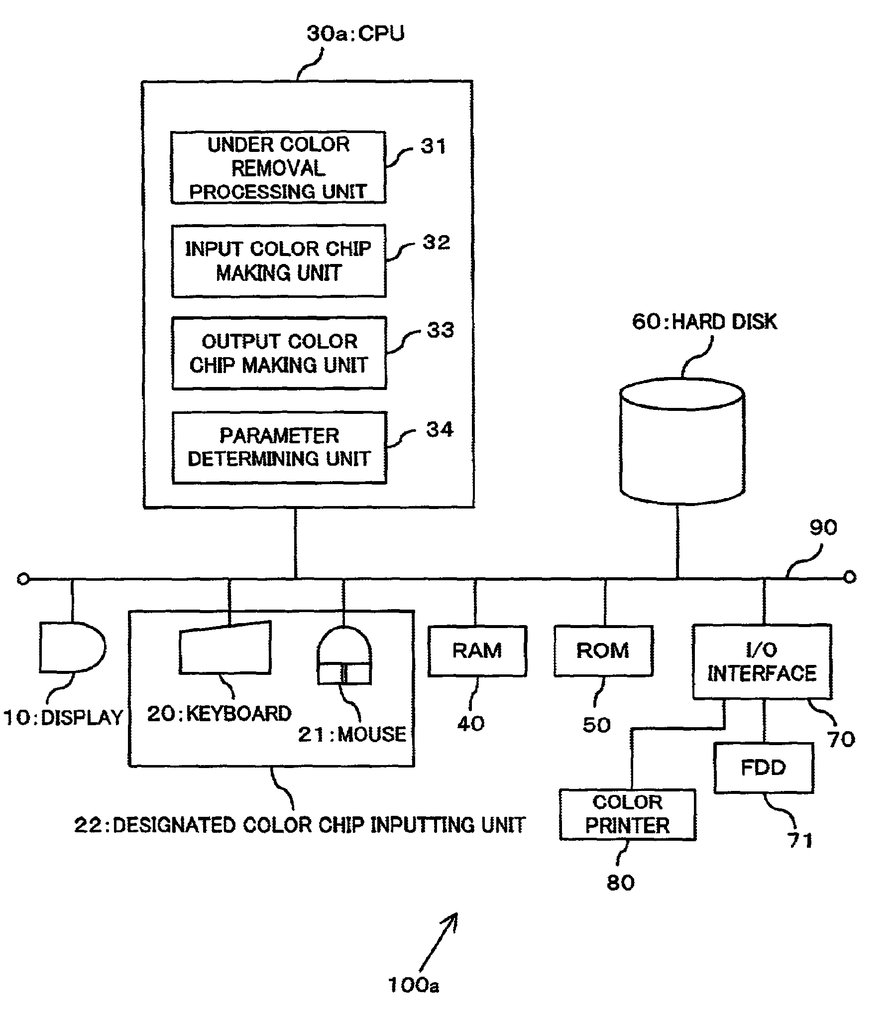
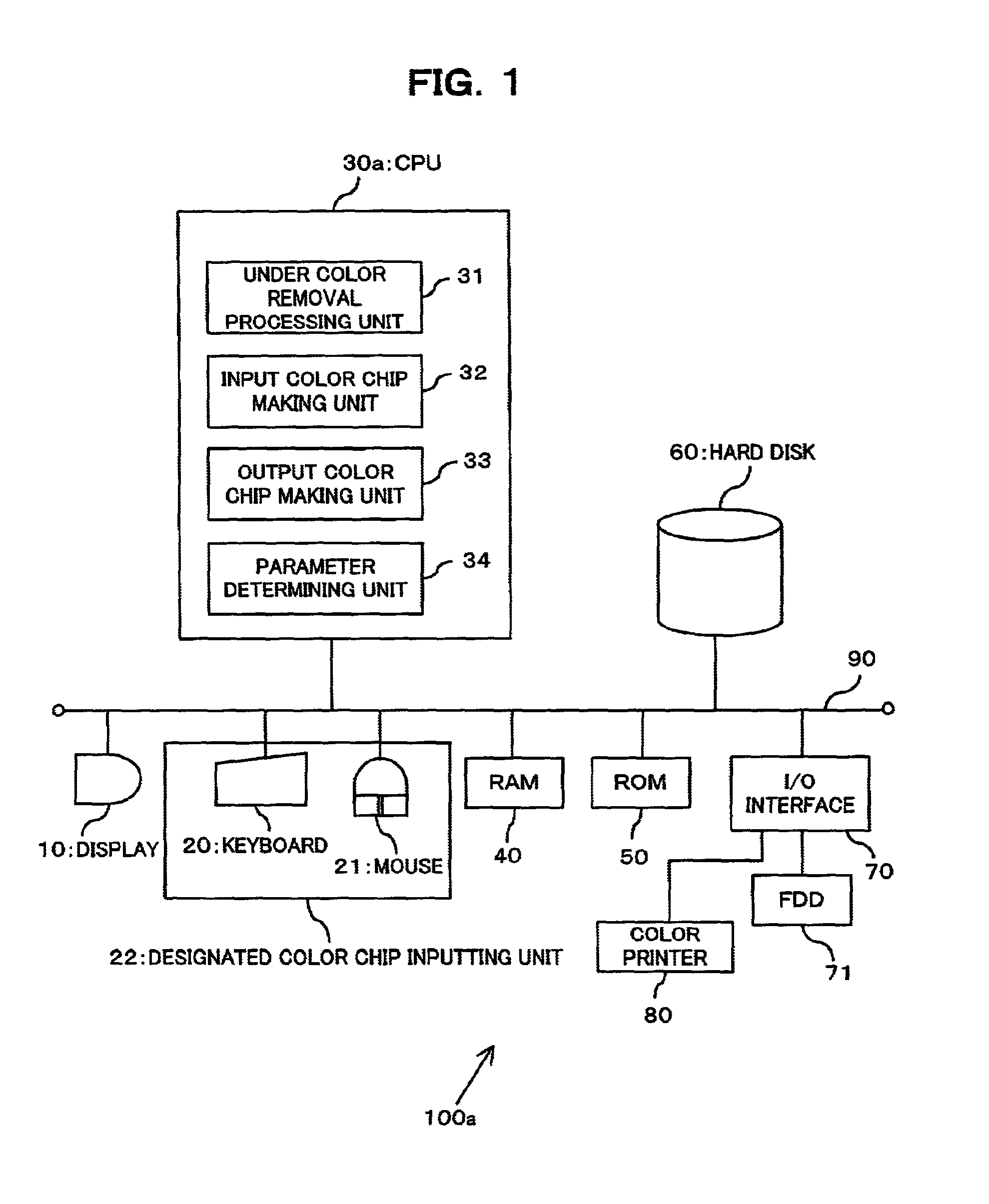
[0105]FIG. 5 is a block diagram showing the hardware arrangement of the color image processing apparatus together with the function arrangement thereof as a second embodiment of the present invention. As shown in FIG. 5, the color image processing apparatus 100b of the second embodiment is arranged to include a CPU 30b instead of the CPU 30a of the color image processing apparatus 100a shown in FIG. 1. Also, the color image processing apparatus 100b of the second embodiment is arranged to include a hard disk 60b instead of the hard disk 60 of the color image processing apparatus 100 a shown in FIG. 1.

[0106]In FIG. 5, like parts attached with the same reference numeral represent the same or substantially the same parts which have been described above. Therefore, they will not be described in detail.

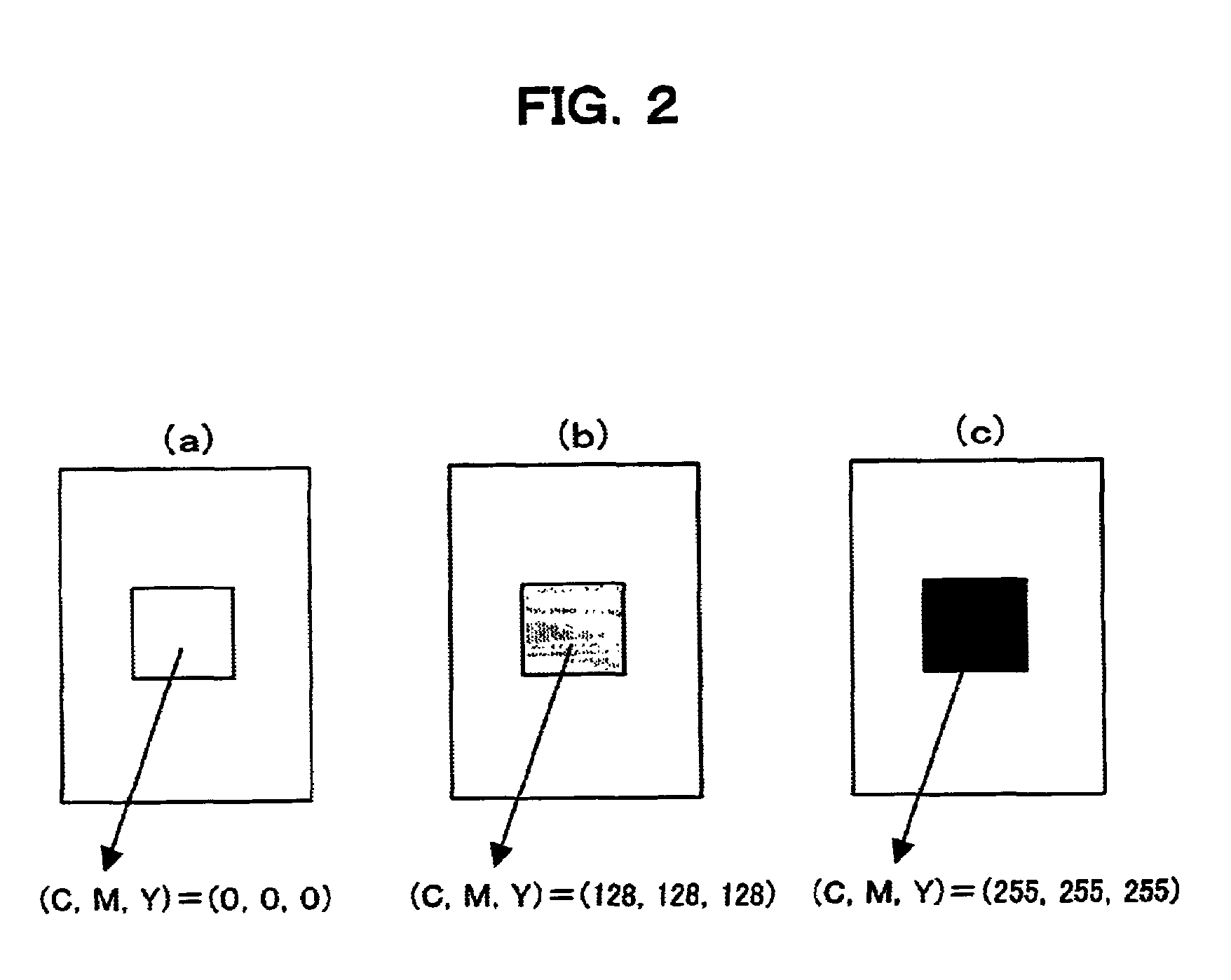
[0107]Also in the second embodiment, respective color components of C, M, Y and K of the color signal are represented by eight-bit digit (ranging from 0...

third embodiment

(C) DESCRIPTION OF THIRD EMBODIMENT

[0150]FIG. 12 is a block diagram showing the hardware arrangement of the color image processing apparatus 100c together with the function arrangement thereof as a third embodiment of the present invention. As shown in FIG. 12, the color image processing apparatus 100c of the third embodiment includes a CPU 30c instead of the CPU 30a of the color image processing apparatus shown in FIG. 1.

[0151]In FIG. 12, components attached with the same reference numerals as those of the aforesaid embodiments represent the same or the substantially the same components. Therefore, they will not be described in detail.

[0152]Also in the third embodiment, respective color components of C, M, Y and K of the color signal are represented by eight-bit digit (ranging from 0 to 255) for convenience.

[0153]Similarly to the CPU 30a of the color image processing apparatus 100a of the first embodiment, the CPU 30c of the color image processing apparatus 100c of the third embodi...


PUM

PropertyMeasurementUnit
coloraaaaaaaaaa
color image processingaaaaaaaaaa
color reproductionaaaaaaaaaa

Abstract

Present invention relates to a color image processing apparatus including an input color chip making unit for making a color chip of the selected color signal as an input color chip, an output color chip making unit for subjecting the selected color signal to the under color removal processing carried out in an UCR processing unit with two or more parameters different from one another, thereby making a color chip of the obtained color signal as an output color chip for each parameter, and a parameter determining unit for selecting among the parameters a parameter which provides the minimum difference between the input color chip and the output color chip, wherein the UCR processing unit subjects the input color signal to the UCR processing by using the parameter selected by the parameter determining unit. With this, a color image desired by a user can be created.

Description

BACKGROUND OF THE INVENTION[0001](1) Field of the Invention[0002]The present invention relates to a color image processing apparatus and a color image processing method, for example, in which an input color signal composed of three components, namely CMY, is subjected to an UCR processing using a K-separation, for example.[0003](2) Description of Related Art[0004]In general, an image forming apparatus such as a printer for outputting color images, characters or the like on a printing medium such as a printing sheet or the like, reproduces a particular color by appropriately blending three chromatic components (color signals) of CMY (Cyan, Magenta, and Yellow) or four chromatic components (color signals) of CMYK.[0005]In such an image forming apparatus, it is desired to reduce the amount of color materials used in color printing as much as possible, since the color material is generally expensive. On the other hand, there is known a method of adjusting color reproduction in which a c...

Claims


Application Information

Patent Timeline
Patent Type & Authority Patents(United States)
IPC IPC(8): G03F3/08G06T1/00B41J2/525H04N1/46H04N1/60
CPCH04N1/6022
Inventor NAGAE, AKIKOUSUI, NOBUAKI
Owner FUJITSU LTD
Features
  • R&D
  • Intellectual Property
  • Life Sciences
  • Materials
  • Tech Scout
  • Unparalleled Data Quality
  • Higher Quality Content
  • 60% Fewer Hallucinations
Learn More