Method and system for providing a dual spin filter

a technology of spin filter and filter body, applied in nanoinformatics, instruments, record information storage, etc., can solve the problems of reducing the signal from the conventional sensor used in the cip configuration, reducing the width of the read track, etc., and achieve the effect of increasing the recording density

Inactive Publication Date: 2006-04-11
WESTERN DIGITAL TECH INC
View PDF1 Cites 199 Cited by
  • Summary
  • Abstract
  • Description
  • Claims
  • Application Information

AI Technical Summary

Benefits of technology

The patent describes a new type of magnetic sensor that can help readers access high-density data on hard drives or other storage devices. This technology uses a special material called a magnetoresistive sensor which helps detect small amounts of magnetic field changes caused by moving parts in these devices. By improving this sensing process, researchers hope they will make it easier for people to read larger volumes of data from smaller machines.

Problems solved by technology

The technical problem addressed in this patent is how to create a magnetoresistor (MR) sensor that provides a stronger signal while being less affected by changes in the read track width of the sensor.

Method used


Image

  • Method and system for providing a dual spin filter
  • Method and system for providing a dual spin filter
  • Method and system for providing a dual spin filter

Examples


Embodiment Construction

[0018]The present invention relates to an improvement in magnetoresistive sensors. The following description is presented to enable one of ordinary skill in the art to make and use the invention and is provided in the context of a patent application and its requirements. Various modifications to the preferred embodiment will be readily apparent to those skilled in the art and the generic principles herein may be applied to other embodiments. Thus, the present invention is not intended to be limited to the embodiment shown, but is to be accorded the widest scope consistent with the principles and features described herein.

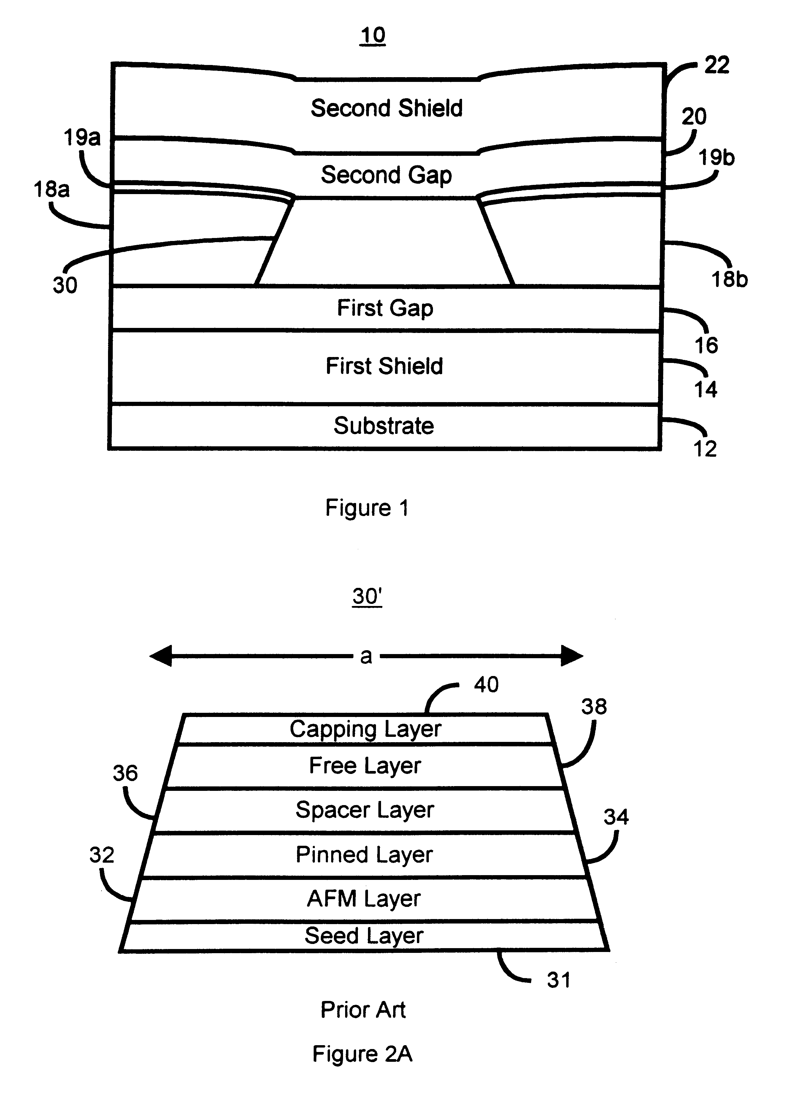
[0019]FIG. 1 is a block diagram of a magnetoresistance (“MR”) head 10. The MR head 10 includes a first shield 14 formed on a substrate 12. The MR head 10 also includes a first gap 16 separating a MR sensor 30 from the first shield 14. The MR head 10 also includes a pair of hard bias layers 18a and 18b. The hard bias layers 18a and 18b magnetically bias layers in the...


PUM


Abstract

A method and system for providing a magnetoresistive sensor is disclosed. The method and system include providing a first pinned layer, providing a free layer having a length, and providing a first spacer layer disposed between the first pinned layer and the free layer. The first spacer layer has a first interface with the first pinned layer. The method and system also include providing a second pinned layer and providing a second spacer layer disposed between the free layer and the second pinned layer. The second spacer layer has a second interface with the second pinned layer. A direction of a current passed through the magnetoresistive sensor is through the first interface, through the second interface, and along at least a portion of the length of the free layer.

Description


Claims


Application Information

Patent Timeline
Owner WESTERN DIGITAL TECH INC
Why Eureka
Try Eureka