System and apparatus for heat dissipation in an electronic device

a technology for electronic devices and systems, applied in lighting and heating apparatus, electrical devices, cooling/ventilation/heating modifications, etc., can solve problems such as damage to electronic devices, achieve simple and low-cost, prevent noise disturbance, and maintain the aesthetic appearance of electronic devices

Inactive Publication Date: 2006-04-11
CANON EURPOPA NV
View PDF8 Cites 17 Cited by
  • Summary
  • Abstract
  • Description
  • Claims
  • Application Information

AI Technical Summary

Benefits of technology

[0015]The invention seeks to resolve the problem of heat dissipation in the electronic devices inserted into the partition walls of a dwelling and connected to a central unit of a home network, in a simple and low-cost way that prevents noise disturbance in the rooms, especially the habitable rooms or office rooms, while at the same time maintaining the aesthetic appearance of the electronic devices.
[0018]Thus, centralized dissipation is possible for several electronic devices of a same network. Furthermore, the infrastructure already present in a home network of this kind is re-utilized. This removes the need for installing another specific infrastructure.
[0026]This enables cool air to enter the electronic device in order to cool the components that it contains.

Problems solved by technology

This accumulation of dust causes damage to this device.

Method used


Image

  • System and apparatus for heat dissipation in an electronic device
  • System and apparatus for heat dissipation in an electronic device
  • System and apparatus for heat dissipation in an electronic device

Examples


Embodiment Construction

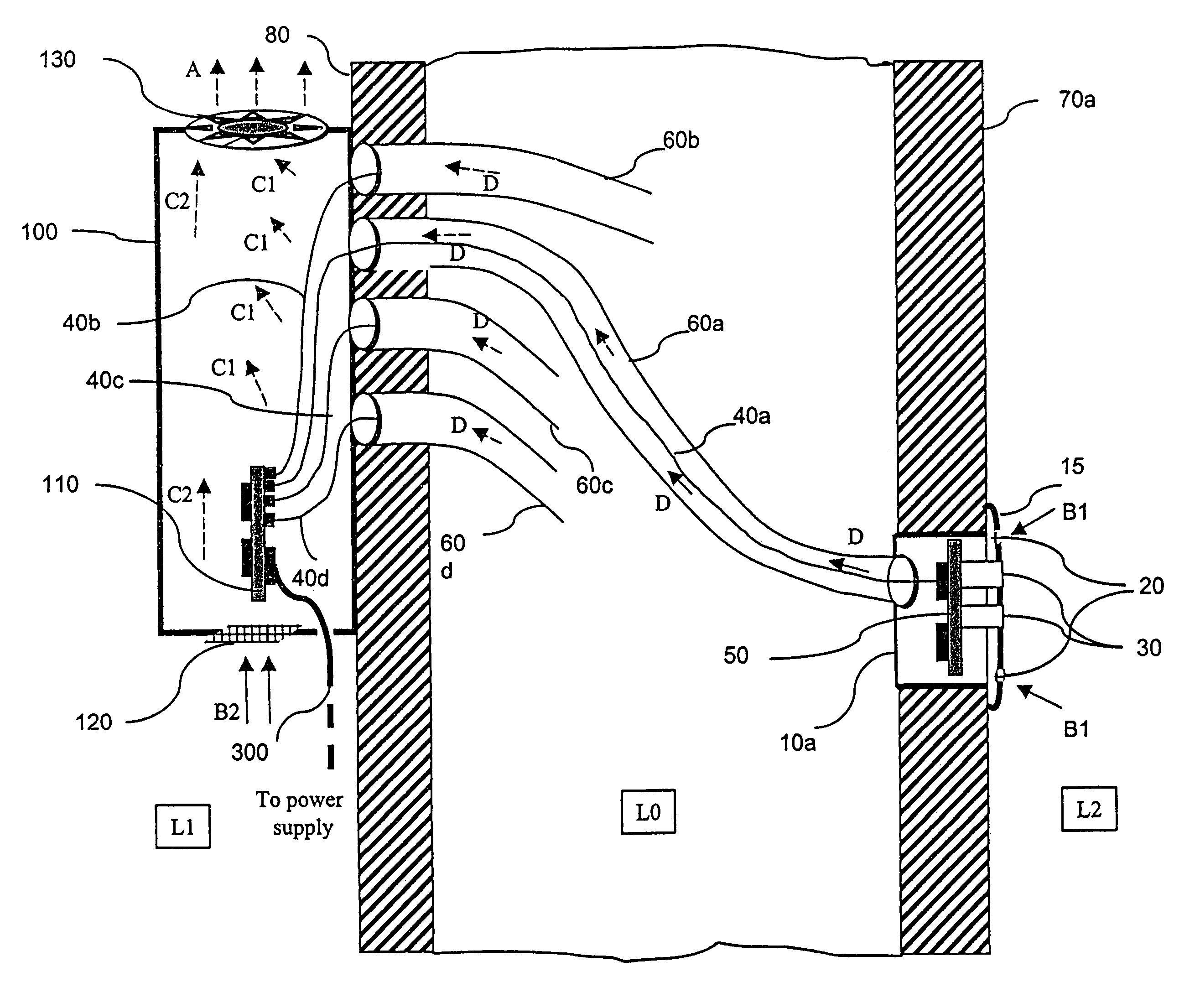
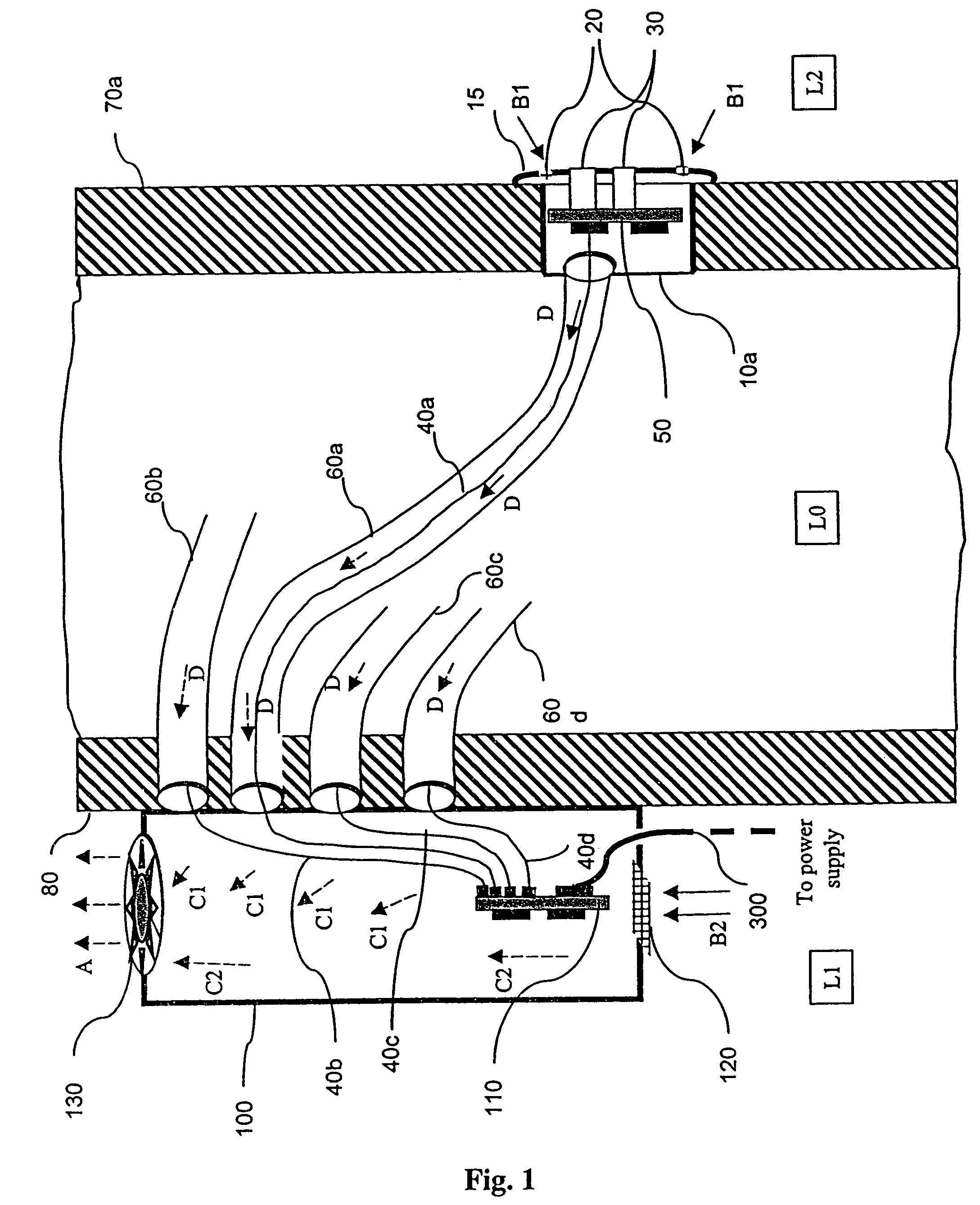
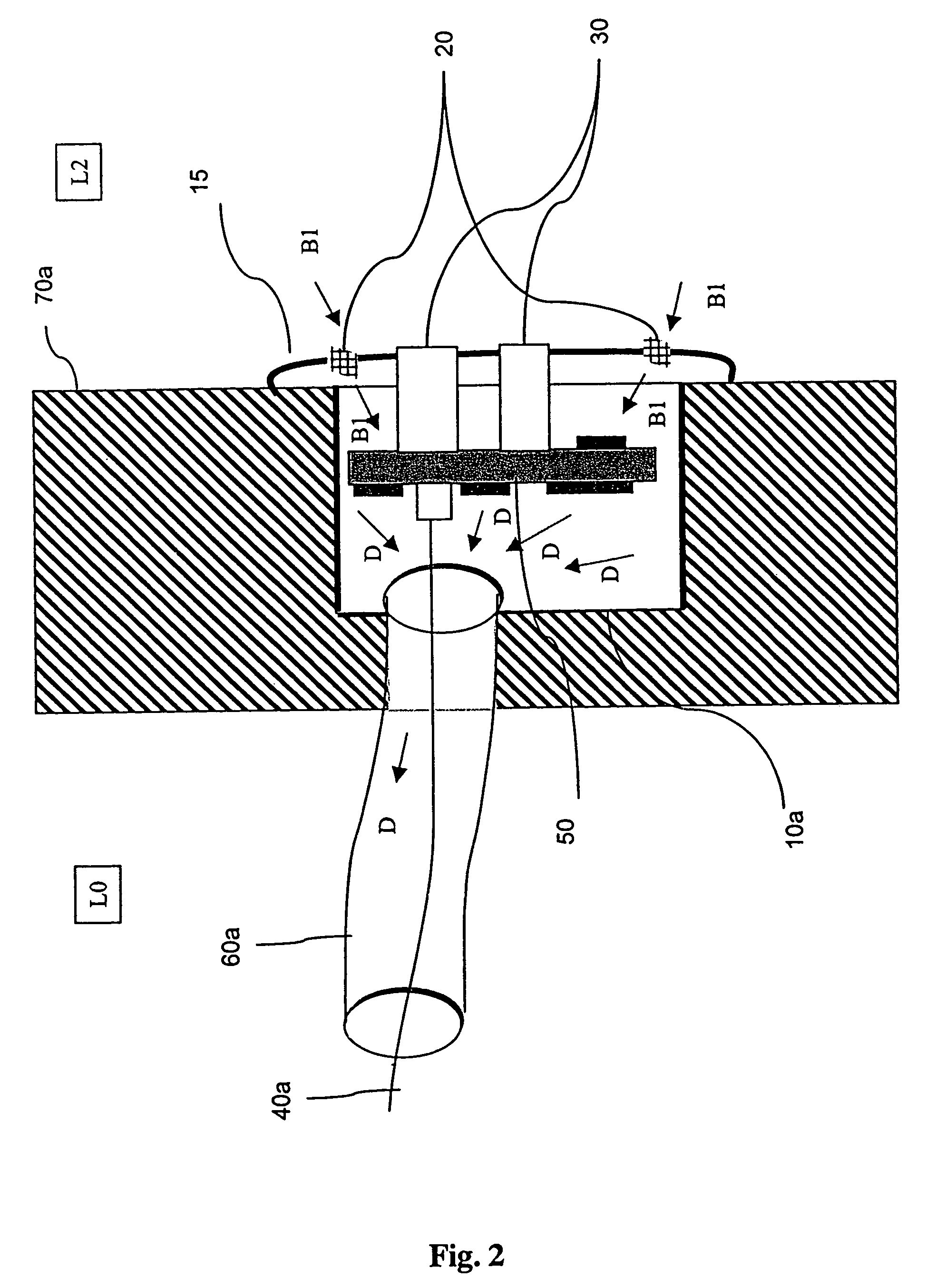
[0044]Referring to FIG. 1, we shall first of all describe the heat dissipation system according to the invention. FIG. 1 shows different elements of a home network such as, for example, a home automation network or again a communications network. This network comprises electronic devices such as, for example, light switches, mains supply connectors or connection interfaces. Only one of these devices is shown in FIG. 1. It is represented schematically by a package 10a comprising an electronic board 50, a front face 15 in which airing holes 20 are made. This package is embedded in a wall or partition 70a of a habitable room L2 and is connected to a central unit 100 by means of a duct 60a. This electronic device shall be described in greater detail with reference to FIG. 2.

[0045]The centralized unit 100 is, for example, located in an annex room of the dwelling such as the garage or a machinery room L1. It is located, for example, beside the electric cabinet of the house. This unit is c...


PUM


Abstract

A system for the dissipation of heat in at least one electronic device in a home network comprises at least one electronic device connected to a central unit (100) by a link (60a, 60b, 60c, 60d) comprising means (40a, 40b, 40c, 40d) able to transport data. This system is such that the heat dissipation is obtained by circulation of air through the link connecting the electronic device to the central unit. More particularly, the system and apparatus of the invention are situated in a home communications network comprising multimedia connection interfaces and an interconnection module.

Description

[0001]This application is a continuation of application Ser. No. 10 / 840,405, filed May 7, 2004 now abandoned.BACKGROUND OF THE INVENTION[0002]1. Field of the Invention[0003]The present invention relates to a system and apparatus for the dissipation of heat in an electronic device, especially a connection interface, in a home network. The invention can be applied especially to a communications network.[0004]There is a growing trend towards the development of home networks. A large number of electronic instruments are grouped together to form a network and thus enable centralized management of the instruments and devices or again enable communications between the devices. Electronic devices such as electric switches, dimmer switches or, again, connection interfaces are used in home networks. These electronic devices are increasingly sophisticated and sometimes fulfill numerous functions in integrating electronic components. These components may be, for example, interior sensors or pro...

Claims


Application Information

Patent Timeline
Patent Type & Authority Patents(United States)
IPC IPC(8): H05K7/20H02G3/04H02G3/08
CPCH02G3/04H05K7/20136H05K7/20H02G3/08
Inventor MERLET, HERVE
Owner CANON EURPOPA NV
Why Eureka
Try Eureka