
Electrophotographic image forming apparatus having residual toner collection

Inactive Publication Date: 2006-04-11
RICOH KK
View PDF29 Cites 16 Cited by
  • Summary
  • Abstract
  • Description
  • Claims
  • Application Information

AI Technical Summary

Benefits of technology

[0015]It is an object of the present invention to provide an image forming apparatus capable of reducing the residual toner and reversely transferred toner for thereby enhancing image quality.
[0016]It is another object of the present invention to provide an image forming apparatus capable of reducing nitric acid and metal nitrates ascribable to discharge products for thereby reducing the blur of an image.

Problems solved by technology

The problem with an electrophotographic image forming apparatus is that discharge from a charger, which uniformly charges the surface of a photoconductive element, produces NOx (nitrogen oxides), ozone and other discharge products.
Forming a thin film on the photoconductive element, such nitric acid and metal oxides absorb moisture and thereby lower the surface resistance of the photoconductive element.
As a result, a latent image formed on the photoconductive element is disturbed with the result that the resulting toner image is blurred.
While an image forming apparatus of the type including a cleaning unit can shave off the film of nitric acid and metal nitrates with a cleaning blade, the cleanerless image forming apparatus cannot do so.
However, none of the conventional cleanerless image forming apparatuses is provided with an implementation for reducing the amount of residual toner to remain on the photoconductive element.
Consequently, in the apparatus of the type effecting development and cleaning at the same time, irregular charging and defective exposure become more likely to occur with an increase in the amount of residual toner, lowering image quality little by little.
In the apparatus of the type using a brush, when much residual toner is present or in a repeat print mode, it is likely that residual toner deposits on the brush in an amount too much to be held by the brush, aggravating irregular charging and defective exposure and lowering image quality little by little.
This scheme, however, lowers printing speed.
A color image forming apparatus has a problem that when toner images of different colors are sequentially transferred from photoconductive elements to a recording medium, intermediate image transfer body or similar subject body, a toner image already transferred to the subject body is reversely transferred to the photoconductive drums.
In the cleanerless system, the toner reversely transferred brings about irregular charging and defective exposure in combination with the residual toner, lowering the image quality of the next color.
Moreover, because the reverse transfer of toner occurs in the preceding step, the toner collected in the developing unit in the following step gives rise to a color mixture problem, further lowering image quality.
The optical catalyst scheme disclosed in Laid-Open Publication 2000-321849 has a problem that the optical catalyst must be positioned in close proximity to the surface of the photoconductive element and charger, i.e., needs an exclusive space in the vicinity of the photoconductive element and charger.

Method used


Image

  • Electrophotographic image forming apparatus having residual toner collection
  • Electrophotographic image forming apparatus having residual toner collection
  • Electrophotographic image forming apparatus having residual toner collection

Examples


Embodiment Construction

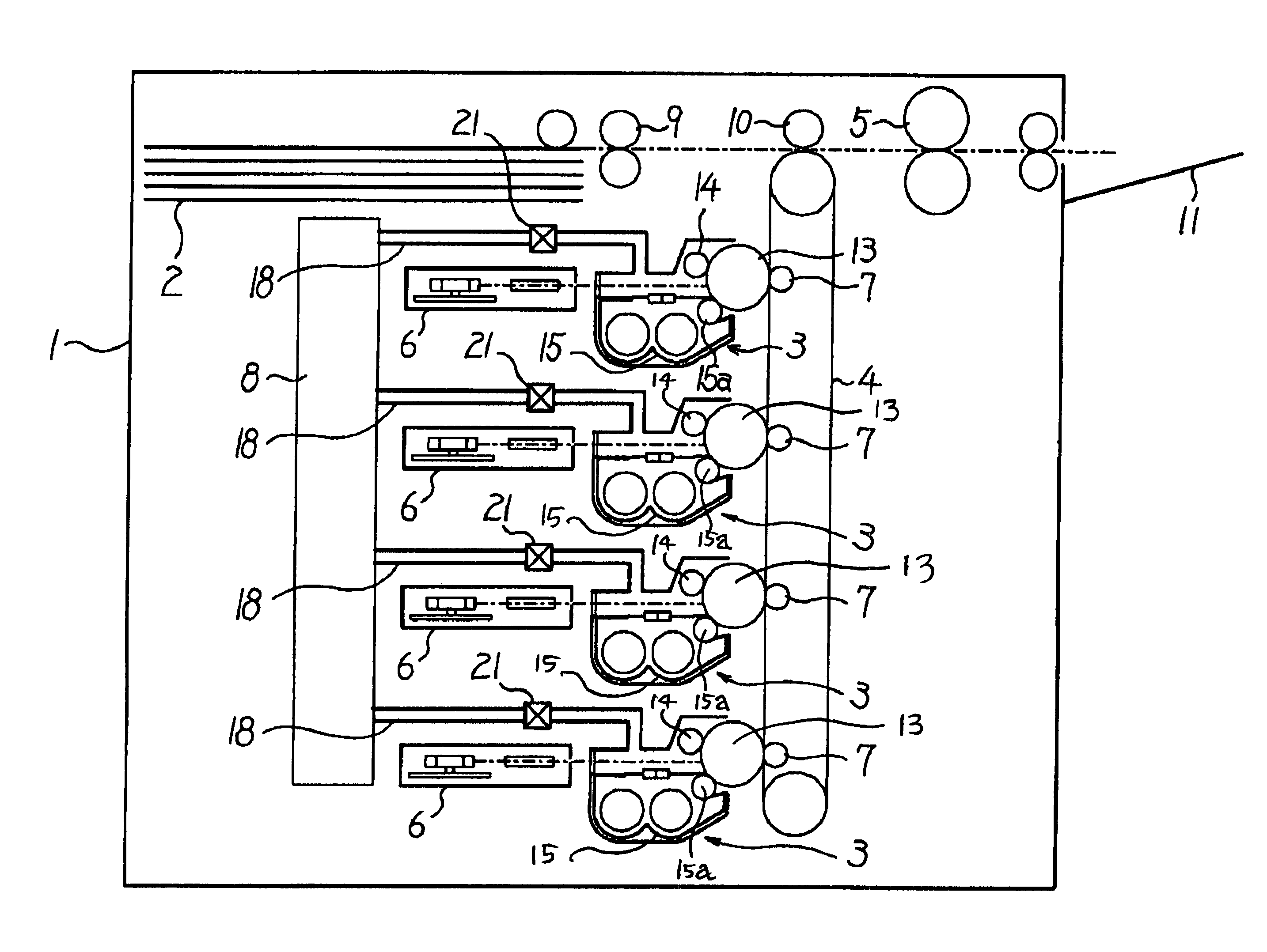
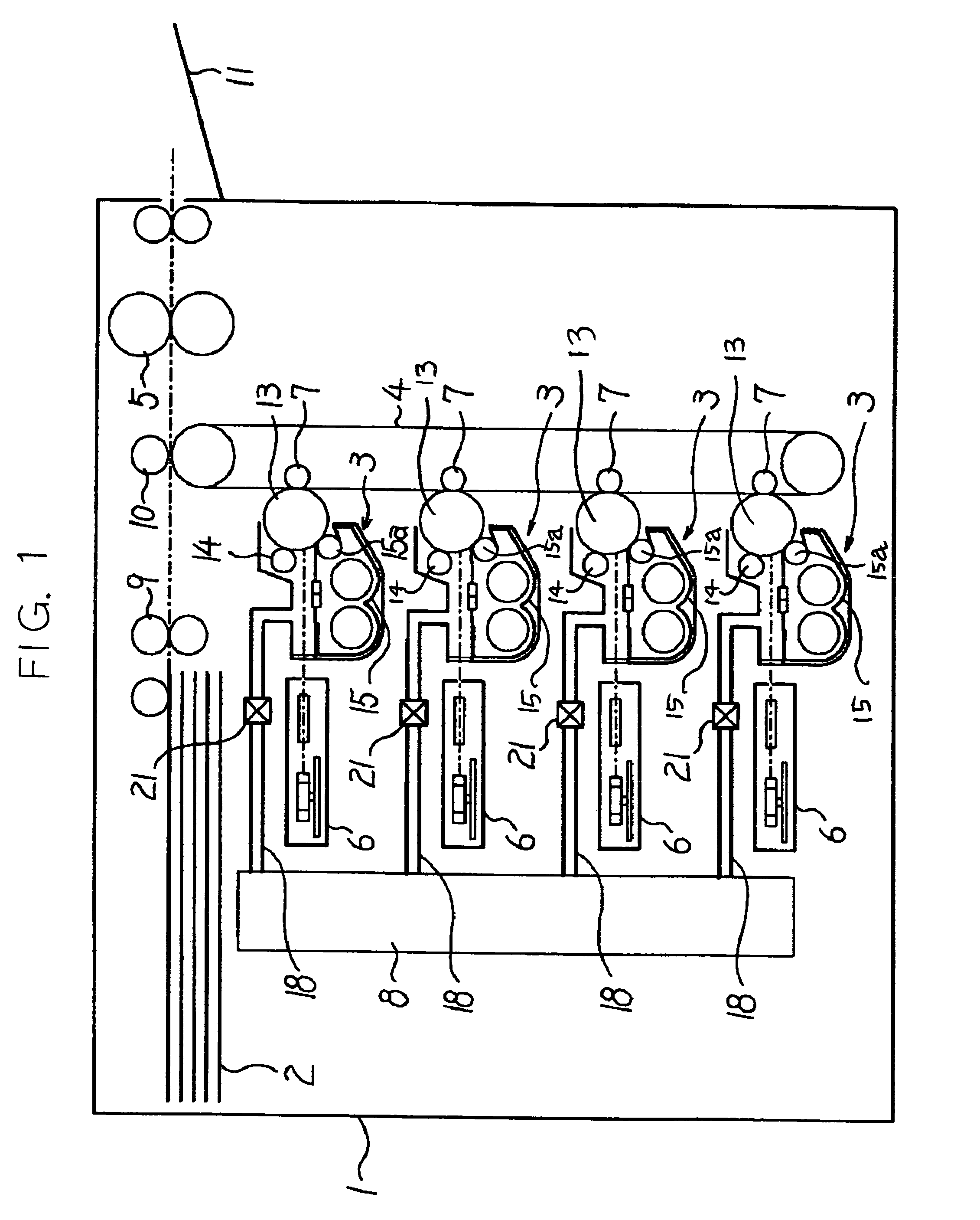
[0022]Referring to FIG. 1 of the drawings, an electrophotographic image forming apparatus embodying the present invention is shown and implemented as a tandem color image forming apparatus by way of example. As shown, the color image forming apparatus includes a casing 1 accommodating a sheet feeding section 2, four image forming modules 3, an intermediate image transfer belt, or subject body, 4, a fixing unit 5, four exposing units 6, four image transferring devices 7, and an air conditioning unit 8. The sheet feeding section 2 is loaded with a stack of sheets or recording media. The four image forming modules 3, removably mounted to the casing, each form a toner image with toner of particular color, i.e., yellow (Y), magenta (M), cyan (C) or black (K). The four exposing units 6 each are assigned to one of the image forming modules 3.

[0023]The four image transferring devices 7 respectively transfer toner images formed by the four image forming modules 3 to the intermediate image tr...


PUM


Abstract

An electrophotographic image forming apparatus of the present invention includes a photoconductive drum provided with a photoconductive layer on its surface. A charger uniformly charges the surface of the drum while an exposing unit exposes the charged surface of the drum to thereby form a latent image on the drum. A developing device develops the latent image with toner by feeding the toner to the drum to thereby produce a corresponding toner image and collects residual toner left on the drum after image transfer. An image transferring device transfer the toner image from the drum to an intermediate image transfer body. An air conditioning unit sends dehumidified, air-controlled air to a space around said photoconductive element.

Description

BACKGROUND OF THE INVENTION[0001]1. Field of the Invention[0002]The present invention relates to an electrophotographic color image forming apparatus capable of protecting images from degradation ascribable to residual toner and reversely transferred toner present on a photoconductive element and reducing blur ascribable to nitric acid and metal nitrates derived from discharge products and depositing on the photoconductive element.[0003]2. Description of the Background Art[0004]Today, a copier, printer, facsimile apparatus or similar electrophotographic image forming apparatus provided with a cleanerless configuration, i.e., not including a cleaning unit is attracting attention from the size and cost reduction standpoint. Japanese Patent Laid-Open Publication Nos. 10-240004 and 2000-321849, for example, each propose a cleanerless image forming apparatus in which a developing unit feeds toner to a photoconductive element for forming a toner image and, at the same time, collects resid...

Claims


Application Information

Patent Timeline
IPC IPC(8): G03G21/20G03B27/00G03G15/01G03G15/02G03G15/08G03G21/18G06F15/00H04N1/29
CPCH04N1/00909H04N1/00981H04N1/00992G03G15/0194G03G21/206G03G21/203G03G15/0173
Inventor MIURA, TETSUROHMIYAWAKI, KATSUAKISAITOU, TAKESHISUDA, TAKEONAKAZATO, YASUSHISUZUKI, YASUO
Owner RICOH KK
Learn More