Multi-story concrete slab construction

a concrete slab and multi-story technology, applied in special buildings, parkings, building repairs, etc., can solve the problems of increasing the man-hours required to complete each floor, increasing the man-hours required for securing the concrete slabs to the framework, and inherently dangerous problems

Inactive Publication Date: 2006-04-18
WALKER & ASSOC SELF STORAGE +1
View PDF35 Cites 34 Cited by
  • Summary
  • Abstract
  • Description
  • Claims
  • Application Information

AI Technical Summary

Problems solved by technology

While this type of construction has proven to be a successful approach, there are inherent drawbacks or problems.
Cranes must be utilized to remove the slabs from the transport trucks and to position the slabs within the framework, which is inherently dangerous due to the size and weight of the concrete slabs.
Securing the slabs to the framework requires many man-hours of labor.
The main problem with this poured-in-place method is that the connector members extend above the surface of the concrete and therefore care must be taken to cover the connector members or to otherwise insure that no concrete is deposited onto the connector members.
The exposed connector members interfere with the screeding operations necessary to finish the surface of each floor and thereby significantly increase the man-hours necessary to complete each floor.
This chipping and cleaning operation is labor and time intensive and may result in damage to the threaded bolts.
If the bolt heads are not sufficiently restrained from turning, the bolts will rotate when the nuts are turned to secure the upper posts to the lower posts and there will be no way to correct this deficiency without chipping into the slab from the underside.
Also, the chipping required to expose the bolts and flanges result in an unsightly crater surrounding each post, which must be filled in or covered.

Method used


Image

  • Multi-story concrete slab construction
  • Multi-story concrete slab construction
  • Multi-story concrete slab construction

Examples


Embodiment Construction

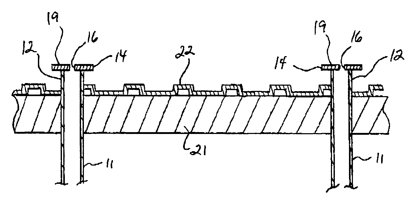
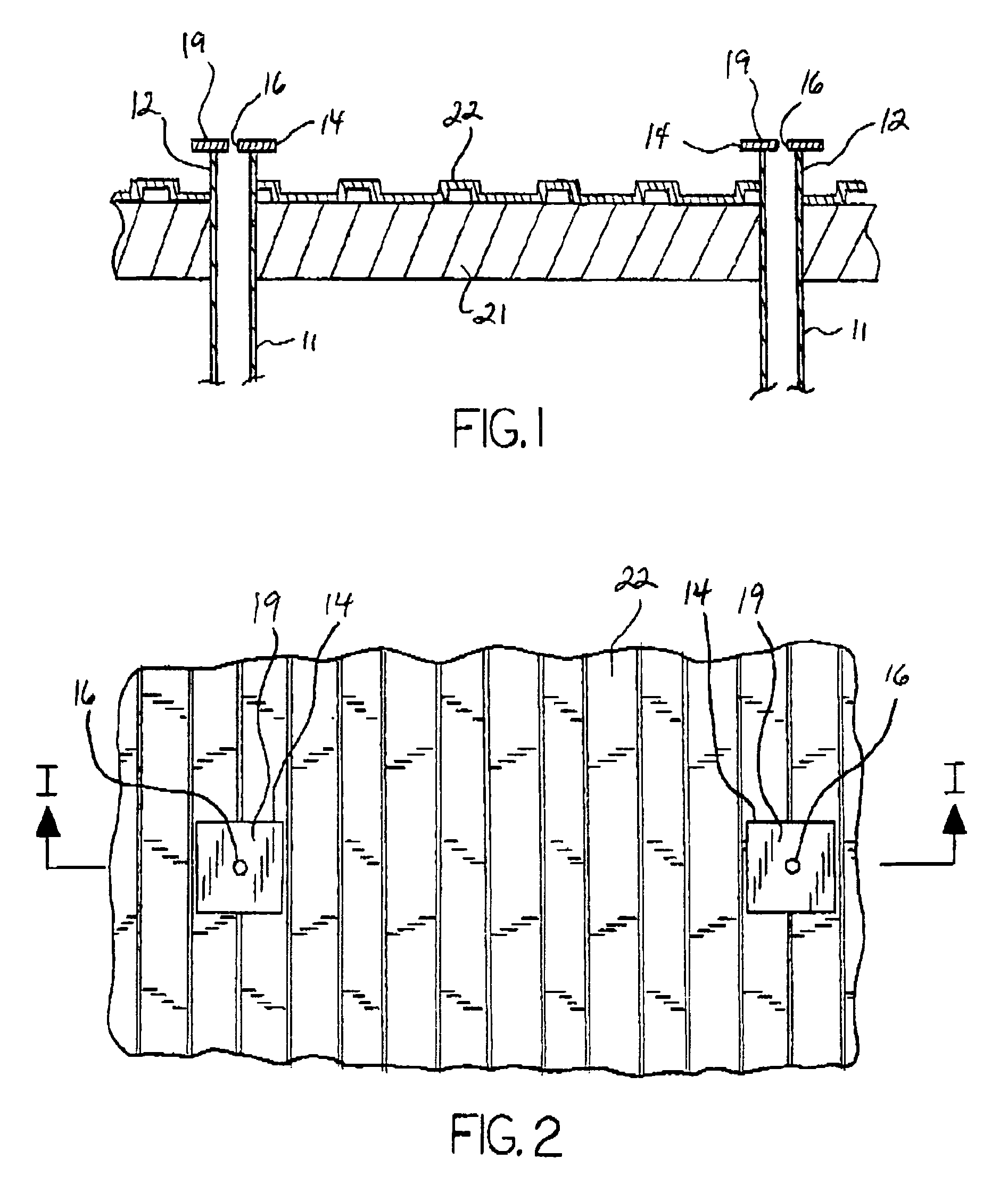
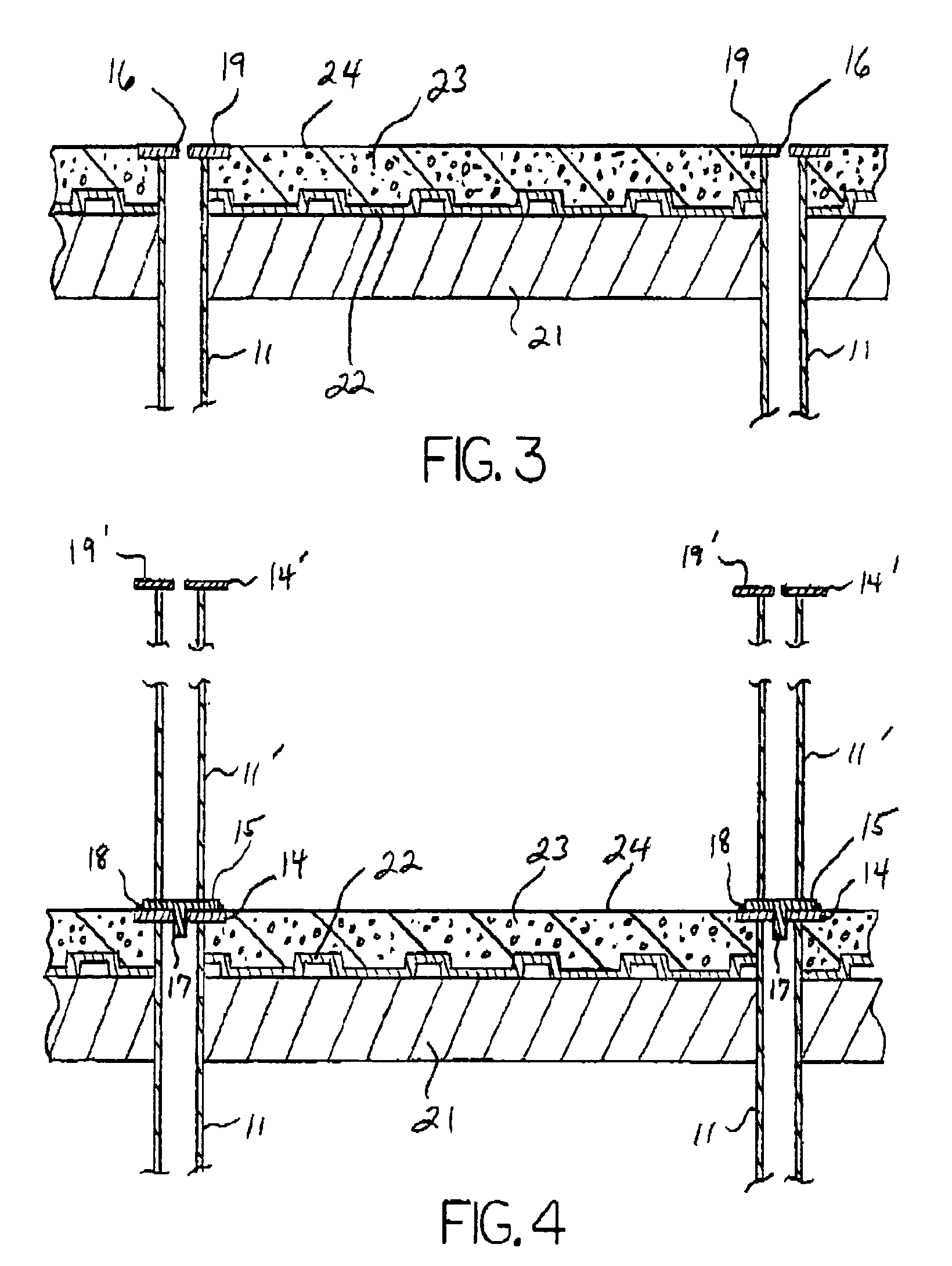
[0015]With reference to the drawings, the invention will now be described in detail with regard for the best mode and preferred embodiment. In general, the invention is a structural system for a multi-story building comprising a number of combined elements and members, and the method of constructing such structural system. More particularly, the invention is such a structural system and method involving a support framework combining vertical post members, horizontal beam members, laterally extensive decking and a poured-in-place concrete floor for at least one upper story of the building above ground level.

[0016]A horizontal foundation slab, typically formed of concrete, is provided to create the ground floor of the multi-story building in known manner. A plurality of vertical post members 11 are secured to or embedded in the foundation in required manner under engineering codes, the post members 11 having sufficient load bearing characteristics as required for the building to be co...


PUM


Abstract

A system and method of constructing multi-story buildings having poured-in-place concrete floors for the upper floors, wherein a set of lower posts is erected, the lower posts having horizontal upper plates on their upper ends each with a centrally disposed aperture. Decking is supported by horizontal beams and defines a form to receive the concrete. The upper plates are masked and concrete is poured and screeded using the upper plates as screed guides, such that the upper surface of the concrete is generally flush with the upper surface of the upper plates. After removal of the masking, a set of upper posts having lower plates with centrally disposed pins are mounted atop the lower posts with the pins inserted into the apertures. The lower plates and upper plates are then welded to joint the lower and upper posts. The cycle is repeated for additional floors.

Description

BACKGROUND OF THE INVENTION[0001]This invention relates generally to a multi-story concrete slab construction system and method, and more particularly to such systems and methods wherein the upper story concrete slabs are poured in place to form the upper story floors and the framing elements are metal posts and beams that support horizontally extensive decking to receive the wet concrete.[0002]It is well known to construct multi-story buildings utilizing concrete floors supported by an interconnected framework of either metal or concrete vertical post members and horizontal beam members. One methodology for constructing such buildings comprises the manufacture of prefabricated concrete slabs. The cured concrete slabs, typically manufactured off-site and transported to the building site, are lifted into position using cranes. The prefabricated slabs are usually provided with embedded connector means such that the slabs may be joined to the framework by mechanical fasteners, welding ...

Claims


Application Information

Patent Timeline
Patent Type & Authority Patents(United States)
IPC IPC(8): E04H1/00E04B1/24
CPCE04B1/24E04B2001/2484E04B2001/246E04B2001/2451
Inventor WALKER, CROCKETT JACKSONBEAVERS, RICHARD BRYAN
Owner WALKER & ASSOC SELF STORAGE
Why Eureka
Try Eureka