Machine for mowing stalk-like crops

a technology of a machine and a stalk is applied in the field of mowing machines for stalk-like crops, which can solve the problems of increasing the weight and length of the machine in the direction of travel, the upper parts of the plant are not supported, and the cost of separate conveyors, so as to facilitate loosening of material jams, improve the guiding of crop material, and improve the division of material flow

Active Publication Date: 2006-04-18
MASCHFAB KEMPER
View PDF24 Cites 12 Cited by
  • Summary
  • Abstract
  • Description
  • Claims
  • Application Information

AI Technical Summary

Benefits of technology

[0015]The described effects of the guide element are particularly advantageous when, in harvesting mode, the cutting and intake mechanisms which are close to the longitudinal mid-plane move outwardly (particularly, rotate outwardly), i.e. they convey the plants first outwardly and then inwardly. With this direction of rotation, the guide element provides improved guiding of the crop material. Another advantage consists of the fact that the intake mechanisms close to the longitudinal mid-plane can particularly well convey materials incoming from cutting and intake mechanisms disposed in the more outward regions, such conveying occurring namely on the rear sides of said inwardly dispose mechanisms.
[0016]As a rule, the flow of materials in the center of the machine is redirected from a transverse movement to a rearwardly directed movement. This redirection occurs preferably by means of inclined conveying drums, which drums also compensate for the height difference between the bottom of the machine and the intake channel of the field chopper. The guide element is advantageously adjusted to the curved shape of this conveying channel. In addition, two rearward surfaces of the guide element, disposed on respective sides of the longitudinal mid-plane of the machine, may be set at a mutual angle such that they form a rearwardly extending edge. In reverse mode, the crop material is deflected leftward or rightward from said edge, which avoids formation of jams.
[0017]A separator element may be provided which improves the division of the material flow when in reverse mode; said element extends rearwardly from the guide element, along the longitudinal mid-plane. In reverse mode, the separator acts in the manner of a knife to divide the crop material into two streams, one flowing leftward and one rightward. The cross section of the separator element is as a rule rectangular.
[0018]In order to return to the material stream plants which have fallen over and have strayed out of the conveying channel, it appears to be advantageous to provide frusto-conically shaped cover elements disposed on the upper side of the cutting and intake mechanisms. The cover elements rotate along with the cutting and intake mechanisms, so that the plants fall down again from said elements. When a cover element extends over the cutting and intake mechanisms, it serves also as a wiper which removes plants from the cover elements and returns them to the stream of material.
[0019]According to a special embodiment of the invention, a rotatable roll is disposed on the upper side of the guide element, which roll extends horizontally, transversely to the direction of travel. The roll may be actively driven or may rotate freely. By rotating, it enables one to avoid material jams, and under active rotation it facilitates loosening of material jams. The cross section of the roll is, in particular, rhomboidal.

Problems solved by technology

The guide elements do not extend above the cutting and intake mechanism, and thus the upper parts of the plants are not supported.
A particular drawback of these machines is that the cutting and intake mechanisms close to the longitudinal mid-plane rotate in a direction which does not allow transport of the plants inwardly at the rear sides of said mechanisms; accordingly, a separate conveying means is needed in order to transport plants from the more outwardly disposed cutting and intake mechanisms toward the center of the machine.
These separate conveyors are costly, and increase the weight and length of the machine in the direction of travel.
In DE 36 23 380 A, plants incoming from outer regions are conveyed to the front side of the cutting and intake mechanisms; such machines have not proven successful in practice.
Thus, they do not provide any support to the upper parts of the plants.
It is effective only when the crop material has already left the conveying channel, and, in reverse mode, it cannot relieve any jam which may have developed.

Method used


Image

  • Machine for mowing stalk-like crops
  • Machine for mowing stalk-like crops
  • Machine for mowing stalk-like crops

Examples


Embodiment Construction

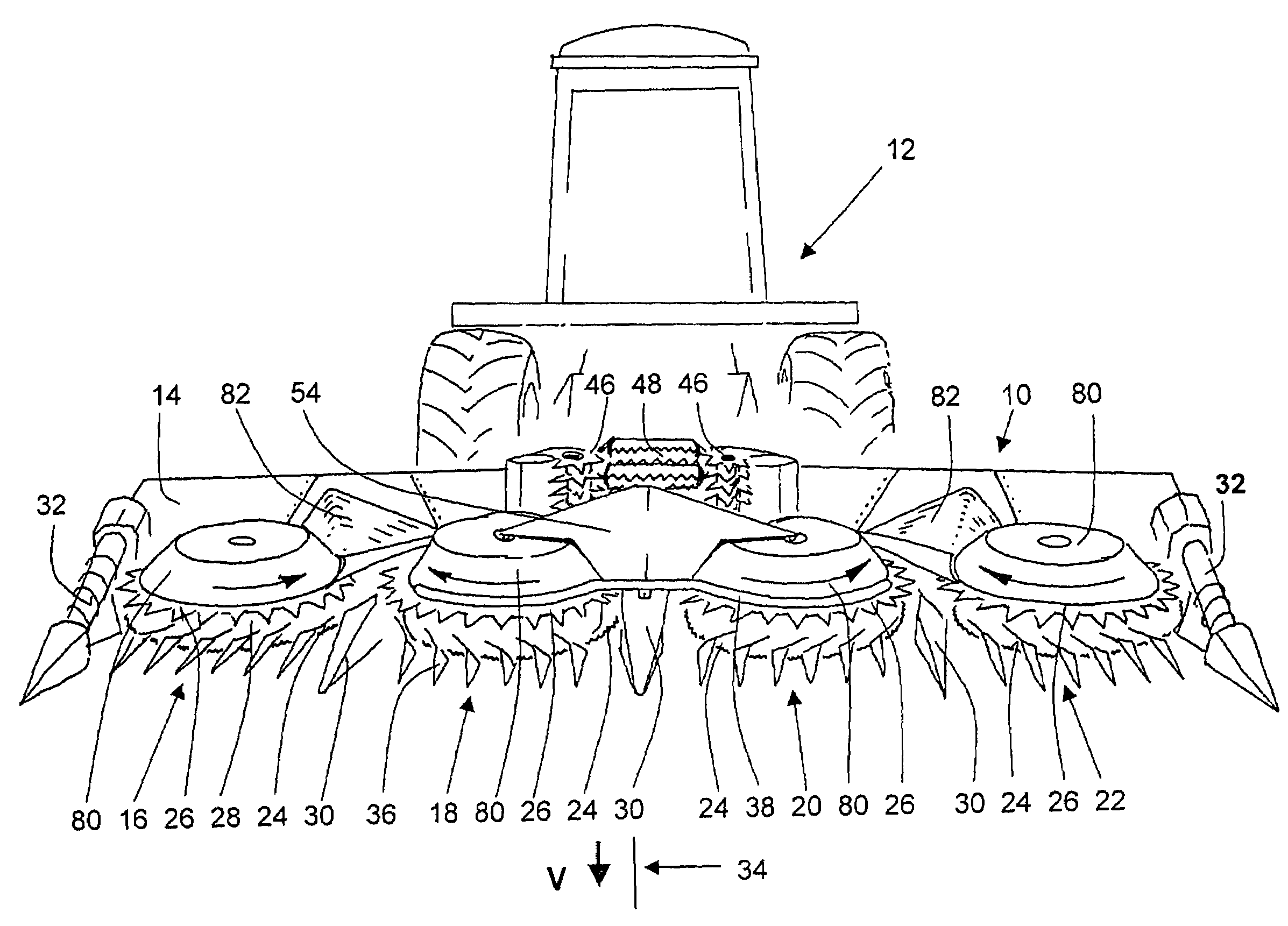
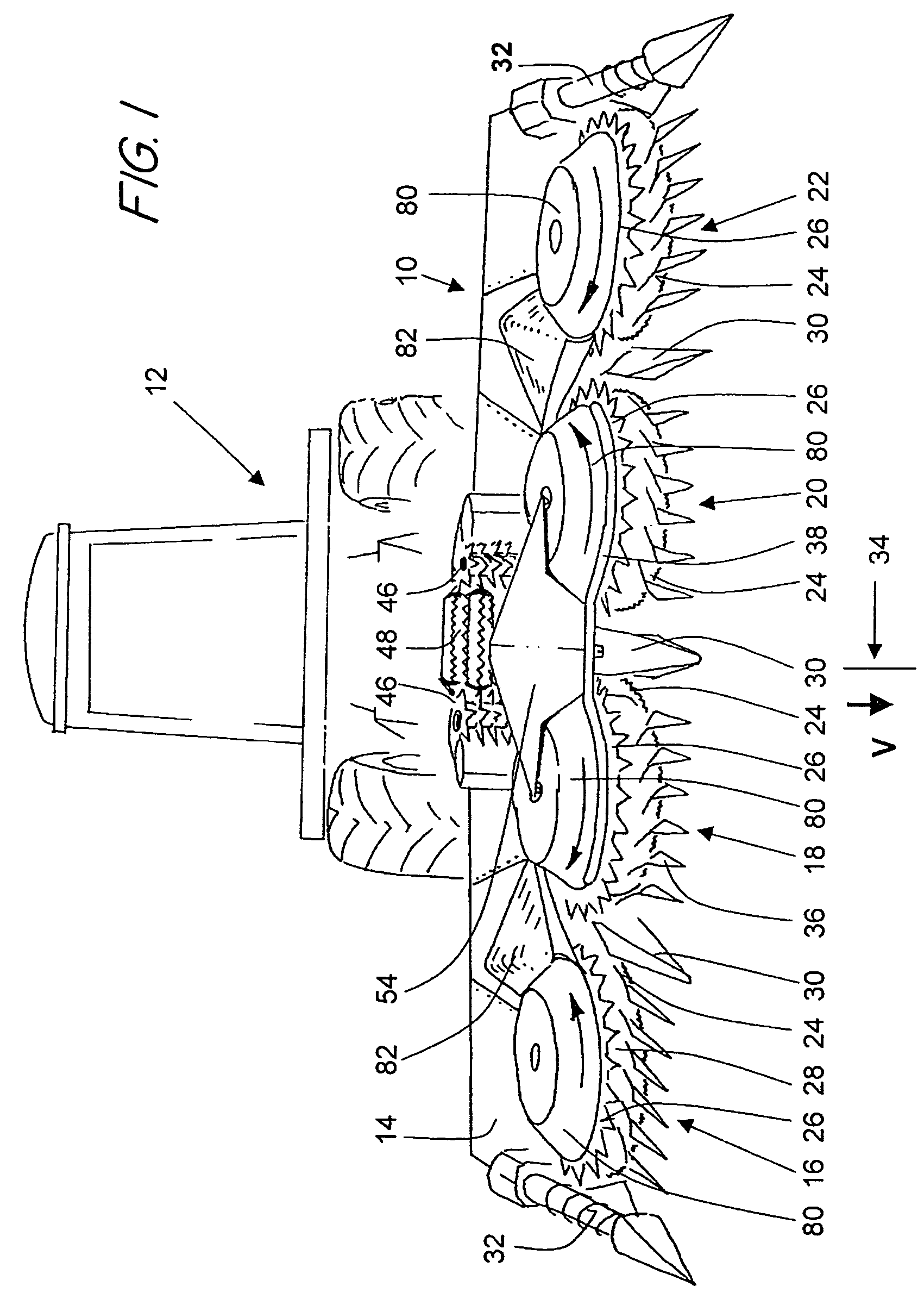
[0027]In FIG. 1, a perspective front view of a machine 10 for mowing of stalk-like crops (particularly corn) is shown. The machine 10 is attached to a self-propelled field chopper 12, and is moved by said chopper in a direction of travel V over a field in which harvesting is being conducted.

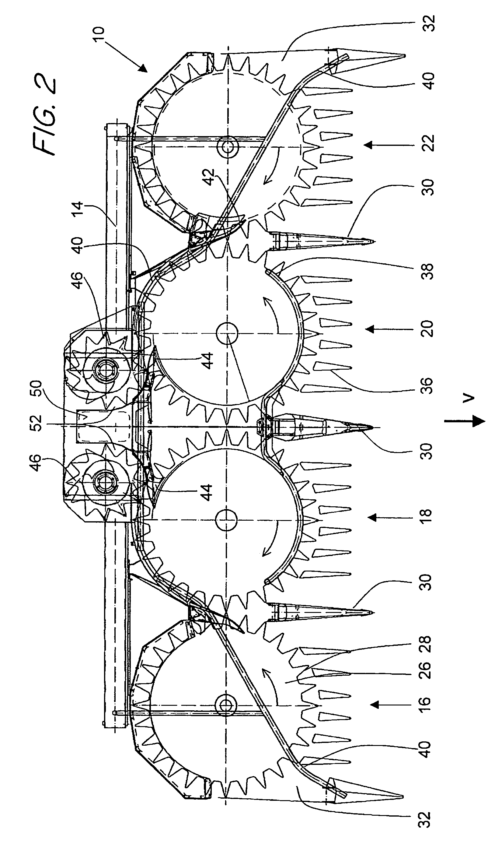
[0028]The machine 10 has a frame 14 on which four cutting and intake mechanisms (16, 18, 20, 22) are mounted side-by-side. Each such cutting and intake mechanism (16, 18, 20, 22) is comprised of a lower, actively rotatable mowing wheel 24 and a rotatable conveying wheel 26 disposed coaxially above said mowing wheel 24. The mowing wheels 24 have sharp teeth on their peripheries or are otherwise provided with sharp implement means, in order to cut off the plant stalk from the stump thereof which remains in the soil. The stalks are engaged in recesses 28 in the conveying wheels 26 and become transported to the field chopper 12 in the manner described below.

[0029]Between neighboring cutting and intak...


PUM


Abstract

A machine is provided for mowing of stalk-like crops, having cutting and intake mechanisms arranged side by side, for cutting and conveying of the crop material, wherewith at least one such cutting and intake mechanism is disposed on each side of the longitudinal mid-plane of the machine. The machine further includes a guide element disposed in the center of the machine above, and at the forward side of, a conveying channel through which plants being harvested are conveyed actively to an intake channel of a field chopper. The guide element includes surfaces which are disposed at a distance from the conveying channel and are disposed relative to the course of the conveying channel so that the surfaces open upward from the conveying channel in a funnel-like manner.

Description

FIELD OF THE INVENTION[0001]The invention relates to a machine for mowing of stalk-like crops, having cutting and intake mechanisms arranged side by side, for cutting and conveying of the crop material, wherewith at least one such cutting and intake mechanism is disposed on each side of the longitudinal mid-plane of the machine, said machine further having a guide element disposed in the center of the machine above, and at the forward side of, a conveying channel in which the plants being harvested are conveyed actively to an intake channel of a field chopper.BACKGROUND OF THE INVENTION[0002]Machines of the type described above are used in agriculture to cut stalk-like crops, e.g. corn plants, from the soil of a field and convey them to a field chopper borne on the machine, in which chopper the plants are chopped and are discharged to a storage container on a trailer. As a rule, such machines have a number of laterally disposed cutting and intake mechanisms, each in the form of an e...

Claims


Application Information

Patent Timeline
Patent Type & Authority Patents(United States)
IPC IPC(8): A01D45/02A01D43/08
CPCA01D43/082
Inventor BRUENING, ULRICHWEITENBERG, KLEMENSHOCKENBECK, LEO SCHULZEHUENING, MARTIN
Owner MASCHFAB KEMPER
Why Eureka
Try Eureka