Tool having easily identified size

a tool and size technology, applied in the field of tools, can solve the problems of time-consuming process, user may not be able to easily locate and identify the correct size, and the width change technique is not practical, and achieve the effect of quick identification of the correct size of the tool

Active Publication Date: 2006-04-18
SHIH LEO
View PDF13 Cites 69 Cited by
  • Summary
  • Abstract
  • Description
  • Claims
  • Application Information

AI Technical Summary

Benefits of technology

[0008]It is an object of the present invention to provide a tool comprising an area disposed on an outer surface, the area being printed in one of two different first colors for identifying the tool as one labeled in either the British system or the metric system; and a numeral as a representation of a size of the tool disposed in the area, the numeral being a stencil so as to expose a metal color of the tool, wherein the numeral has a second color different from the first color of the area for providing a contrast of the numeral to other portions of both the area and the tool. By utilizing the present invention, it is possible of quickly identifying the correct size of the tool prior to use or storage.
[0009]It is another object of the present invention to provide a tool comprising an area disposed on an outer surface, the area being printed in one of two different first colors for identifying the tool as one labeled in either the British system or the metric system; and a numeral as a representation of a size of the tool disposed in the area, the numeral being a stencil and having a color different from the first color of the are printed therein so as to provide a contrast of the numeral to other portions of both the area and the tool. By utilizing the present invention, it is possible of quickly identifying the correct size of the tool.
[0010]It is still another object of the present invention to provide a tool comprising an enclosed embossment disposed on an outer surface, the embossment being printed in one of two different first colors for identifying the tool as one labeled in either the British system or the metric system; and a numeral as a representation of a size of the tool disposed in the area by printing, the numeral having a second color different from the first color of the embossment for providing a contrast of the numeral to other portions of both the area and the tool. By utilizing the present invention, it is possible of quickly identifying the correct size of the tool.
[0011]It is a further object of the present invention to provide a tool comprising an area disposed on an outer surface, the area being printed in one of two different first colors for identifying the tool as one labeled in either the British system or the metric system; a numeral as a representation of a size of the tool disposed in the area, the numeral having a second color different from the first color of the area for providing a contrast of the numeral to other portions of both the area and the tool; and a trademark being formed by cutting through the area or printing on the area, the trademark having a third color different from both the first color of the area and the second color. By utilizing the present invention, it is possible of quickly identifying the correct size of the tool and the trademark.

Problems solved by technology

This is a time consuming process.
Further, a user may not be able to easily locate and identify the correct size since both the size and the tool have the same color.
However, width change technique is not practical because a user can hardly distinguish one size from an adjacent size due to very small width change therebetween.
Unfortunately, this is not necessary since a visual observation is sufficient.
Thus, the first prior art is not advantageous.
As such, the second prior art can cause confusion for an ordinary user.
Thus, it is impractical.
Unfortunately, the second prior art fails to achieve the above goal.
However, such arrangement may be too complicated, resulting in an increase in the manufacturing cost.

Method used


Image

  • Tool having easily identified size
  • Tool having easily identified size
  • Tool having easily identified size

Examples


Embodiment Construction

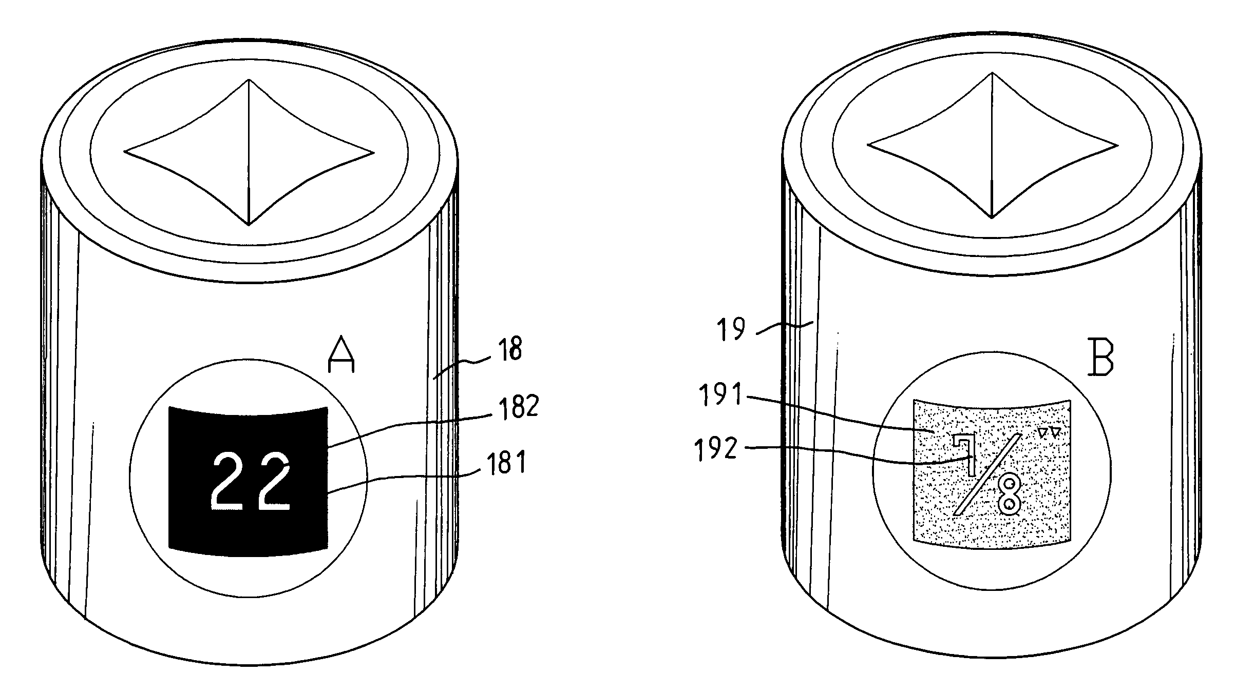
[0032]Referring to FIGS. 4 and 5, there is shown a tool (e.g., sleeve) having an arrangement for easily identifying a size thereof in accordance with a first preferred embodiment of the invention. A rectangular area 181 having a color different from that of the remaining portion of the sleeve 18 of the metric system is printed on an outer surface of the sleeve 18. A numeral 182 (e.g., 22 as shown) is formed by cutting through the rectangular area 181 so as to form a stencil for exposing the color of the metal sleeve 18 and providing a contrast of the numeral 182 to other portions of the sleeve 18. Likewise, A rectangular area 191 having a color different from that of the remaining portion of the sleeve 19 of the British system is printed on an outer surface of the sleeve 19. A numeral 192 (e.g., ⅞″ as shown) is formed by cutting through the rectangular area 191 so as to form a stencil for exposing the color of the metal sleeve 19 and providing a contrast of the numeral 192 to other ...


PUM


Abstract

A tool comprises a surface area, the area being printed in one of two different first colors for identifying the tool as one labeled in either the British system or the metric system, and a numeral as a representation of a size of the tool disposed in the area, the numeral having a second color different from the first color of the area for providing a contrast of the numeral to other portions of both the area and the tool. The correct size of the tool thus can be quickly identified. Moreover, a number of embodiments are made possible.

Description

BACKGROUND OF THE INVENTION[0001]1. Field of the Invention[0002]The present invention relates to tools and more particularly to a tool having an arrangement for easily identifying a size thereof by different colors and other techniques.[0003]2. Description of Related Art[0004]Conventionally, a tool is classified by size of the metric system or the British system. It is typical for a user to visually identify the size of a tool. This is a time consuming process. Further, a user may not be able to easily locate and identify the correct size since both the size and the tool have the same color. For solving the above problem, a number of documents have been disclosed as detailed below.[0005]A Taiwanese Patent Published No. 77,210,372 as shown in FIG. 1 disclosed a sleeve 10 having its size labeled in the metric system (or a sleeve 11 having its size labeled in the British system). An annular recess 101 is formed around the sleeve 10 and an annular recess 111 is formed around the sleeve ...

Claims


Application Information

Patent Timeline
Patent Type & Authority Patents(United States)
IPC IPC(8): B25B13/02B25B13/56
CPCB25B13/56Y10S81/05
Inventor SHIH, LEO
Owner SHIH LEO
Why Eureka
Try Eureka