Start control apparatus for internal combustion engine

a technology of start control and internal combustion engine, which is applied in the direction of electric control, engine starters, machines/engines, etc., can solve the problems of increasing the power consumption of the electric motor

Inactive Publication Date: 2006-04-18
TOYOTA JIDOSHA KK
View PDF19 Cites 10 Cited by
  • Summary
  • Abstract
  • Description
  • Claims
  • Application Information

AI Technical Summary

Benefits of technology

[0009]The present invention has been made in view of the above-described problem. An object of the present invention is to provide a technology that enables efficient starting of a port injection type internal combustion engine.

Problems solved by technology

Hence, the electric motor tends to have high rated performance and power consumption of the electric motor also tends to become large accordingly.
In particular, in the system in which the operation of the internal combustion engine is automatically stopped while the vehicle is at rest (i.e. a so-called idle stop system), since there is a possibility that stopping and starting of the driving of the internal combustion engine are repeated frequently, there is a concern that the load applied on the electric motor will become large to thereby further increase the power consumption of the electric motor.
The above-described prior art technology is effective for internal combustion engines provided with a fuel injection valve adapted to inject fuel directly into a cylinder (i.e. so-called direct injection type internal combustion engines), but it is difficult to say that this technology is effective for internal combustion engines provided with a fuel injection valve adapted to inject fuel to an intake port of a cylinder (i.e. so-called port injection type internal combustion engines).

Method used


Image

  • Start control apparatus for internal combustion engine
  • Start control apparatus for internal combustion engine
  • Start control apparatus for internal combustion engine

Examples


embodiment 1

[Embodiment 1]

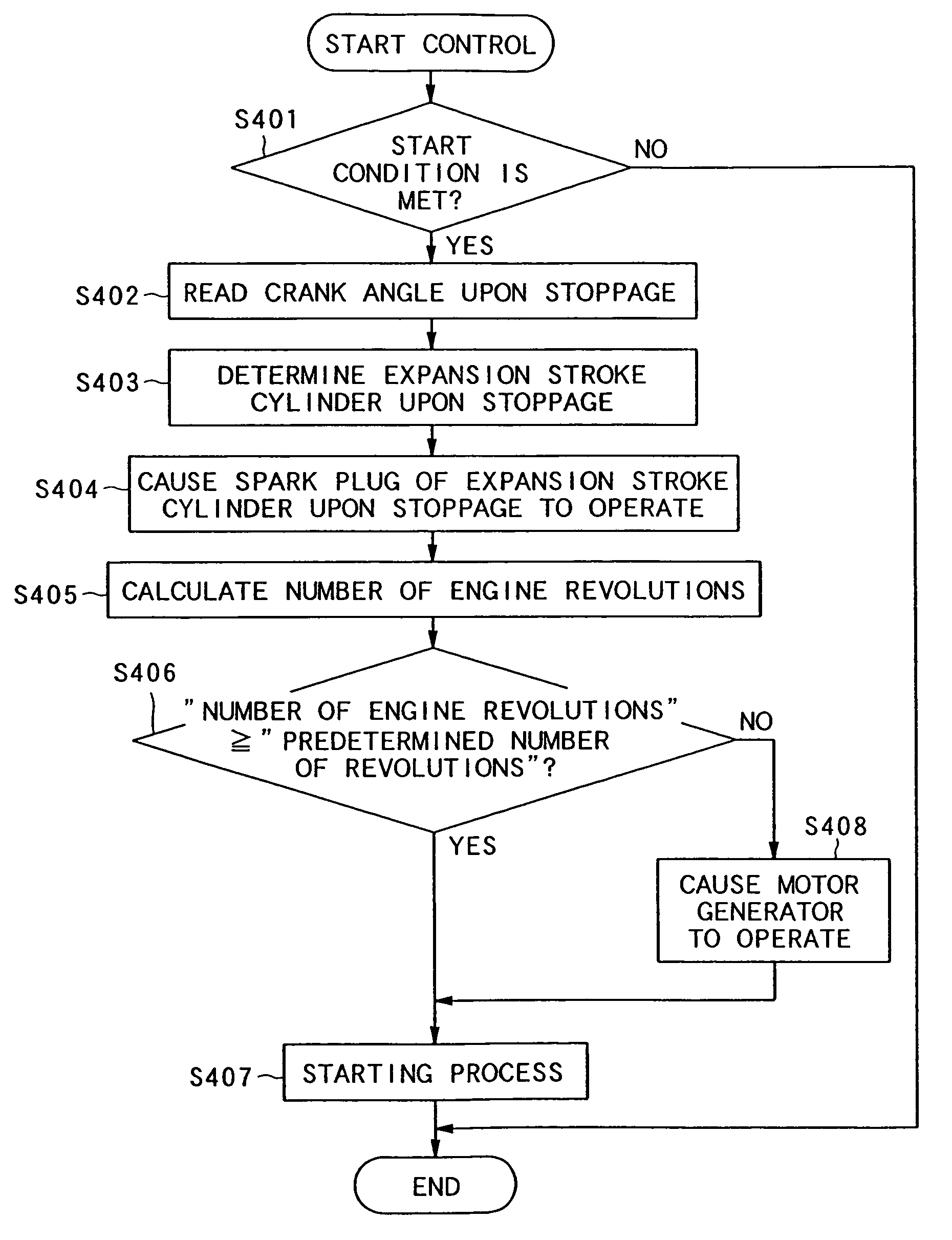
[0090]A first embodiment of the start control apparatus for an internal combustion engine according to the present invention will be described firstly with reference to FIGS. 1 to 5.

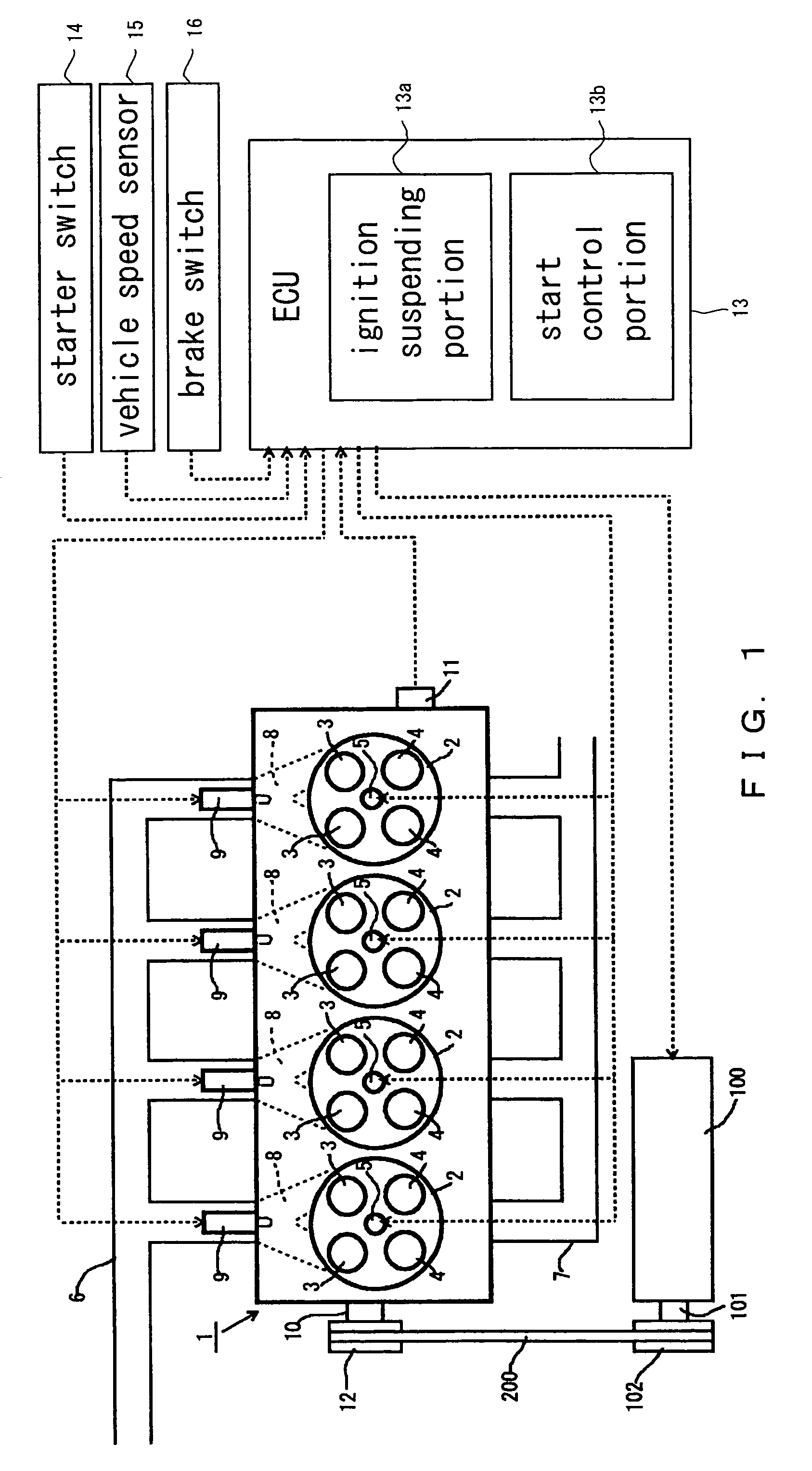
[0091]FIG. 1 schematically shows an internal combustion engine to which the present invention is applied. The internal combustion engine 1 shown in FIG. 1 is a four-stroke cycle gasoline engine in which four cylinders 2 are arranged in a line.

[0092]Each of the cylinders 2 of internal combustion engine 1 is provided with an intake valve 3, an exhaust valve 4 and an ignition plug 5.

[0093]The internal combustion engine 1 is connected with an intake passage 6 and an exhaust passage 7. The intake passage 6 is in communication with each of the cylinders 2 of the internal combustion engine 1 via an intake port 8.

[0094]A fuel injection valve 9 is attached to each intake port 8. The fuel injection valve 9 can inject fuel in the interior of the intake port 8.

[0095]In addition, a crank position sensor...

embodiment 2

[Embodiment 2]

[0172]Next, a second embodiment of the start control apparatus for an internal combustion engine according to the present invention will be described with reference to FIGS. 6 to 8. In the following, the structures that are different from those in the first embodiment will be described, and descriptions of the same structures will be omitted.

[0173]The difference between this embodiment and the above-described first embodiment is that while in the above-described first embodiment the fuel injection valves 9 of all of the cylinders 2 are caused to operate during the time period required for engine stop, in this embodiment the expansion stroke cylinder upon stoppage 2 is estimated and only the fuel injection valve 9 of the estimated expansion stroke cylinder upon stoppage 2 is caused to operate during the time period required for engine stop.

[0174]As shown in FIG. 6, in the ECU 13, a driving stop portion 13c, an estimate portion 13d, a fuel injection control portion 13e, ...

embodiment 3

[Embodiment 3]

[0215]Next, a third embodiment of the start control apparatus for an internal combustion engine according to the present invention will be described with reference to FIGS. 9 to 11. In the following, the structures that are different from those in the first embodiment will be described, and descriptions of the same structures will be omitted.

[0216]The difference between this embodiment and the above-described first embodiment is that while in the above-described first embodiment the fuel injection valves 9 of all of the cylinders 2 are operated during the time period required for engine stop so that unburned air-fuel mixture is sealed in the interior of the cylinder 2 that is on the expansion stroke when the rotation of the crankshaft 10 stops, in this embodiment the fuel injection valve 9 of a specific cylinder 2 is caused to operate just before the rotation of the crankshaft 10 stops and the rotation of the crankshaft 10 is stopped at the time when the aforementioned...


PUM


Abstract

A start control apparatus for an internal combustion engine according to the present invention is characterized by that in a port injection type internal combustion engine, fuel is supplied in the interior of a cylinder that is in its compression stroke or expansion stroke upon stoppage of the internal combustion engine, and upon the next start of the internal combustion engine, the fuel in the interior of the aforementioned cylinder is burned to rotate the engine output shaft utilizing the pressure generated when the fuel is burned. Thus, the torque required for cranking the internal combustion engine is reduced and the load applied on a starter apparatus such as a starter motor is reduced.

Description

[0001]This is a continuation-in-part application of Application PCT / JP03 / 11161, filed Sep. 1, 2003, which was published under PCT Article 21(2) in Japanese.BACKGROUND OF THE INVENTION[0002]1. Field of the Invention[0003]The present invention relates to an internal combustion engine mounted on an a vehicle or the like, and in particular to a start control technology for an internal combustion engine[0004]2. Description of the Related Art[0005]In recent years, an electric motor is generally used as means for rotationally driving (i.e. cranking) a crankshaft upon starting an internal combustion engine. It is necessary for such an electric motor to rotationally drive the crankshaft while resisting a gas compression force or frictions generated in various portions of the internal combustion engine. Hence, the electric motor tends to have high rated performance and power consumption of the electric motor also tends to become large accordingly.[0006]In particular, in the system in which th...

Claims


Application Information

Patent Timeline
Patent Type & Authority Patents(United States)
IPC IPC(8): F02N17/00F02N15/00F02D17/00F02D29/02F02D41/04F02D41/06F02D41/34F02D41/36F02D43/00F02D45/00F02N11/08F02N19/06
CPCF02D17/00F02D41/009F02N99/006F02D41/062F02B2275/16F02D41/042Y02T10/123F02N19/005F02N2019/007Y02T10/12F02D29/02F02D41/06
Inventor TSUJI, KIMITOSHIKUSAKA, YASUSHIKATAOKA, KENJIASADA, TOSHIAKIMITANI, SHINICHI
Owner TOYOTA JIDOSHA KK
Why Eureka
Try Eureka