Hydrostatic Power Unit

a power unit and hydrostatic technology, applied in the direction of combination engines, belts/chains/gearings, and control of gears, can solve the problems of occupying a large space, reducing the pressure of the pressure valve, and no charge pressure or volume flow available in the charging pressure circuit, so as to achieve the elimination of large and expensive valves, the effect of less effort or expense, and less effort or expens

Inactive Publication Date: 2015-02-26
LINDE HYDRAULICS
View PDF4 Cites 9 Cited by
  • Summary
  • Abstract
  • Description
  • Claims
  • Application Information

AI Technical Summary

Benefits of technology

[0016]The invention accomplishes this object in that a supplemental positioning piston device is provided which is in an operative connection with the displacement volume control device for control of the displacement volume of the power unit, and which can be pressurized directly by the pressure present in the hydraulic accumulator. The power unit can be adjusted toward an increase in the displacement volume to start the internal combustion engine by a connection of the supplemental positioning piston device with the hydraulic accumulator. The invention, therefore, teaches that, in addition to the actuator and control device and positioning piston device supplied with pressure and hydraulic fluid from the charging pressure circuit, a supplemental positioning piston device is provided, with which the displacement volume of the power unit can be adjusted when the internal combustion engine is shut off, and which is pressurized directly at the increased pressure level and with the pressure from the hydraulic accumulator. Because the supplemental positioning piston device is pressurized directly with the pressure of the hydraulic accumulator, no additional pressure reducing valve is necessary to reduce the pressure in the hydraulic accumulator to the charge pressure level and no additional shutoff valve to prevent an outflow or discharge of the charge pressure generated from the hydraulic accumulator via the pressure-reducing valve into the charging pressure circuit, which means that large and expensive valves can be eliminated. The power unit of the invention, with the supplemental positioning piston device, therefore makes possible, with little added effort or expense and requiring only a little additional space for installation of the components, an adjustment of the power unit when the internal combustion engine is shut off for the startup of the internal combustion engine by operating the power unit as a motor.

Problems solved by technology

When the internal combustion engine is shut off, however, there is no charge pressure or volume flow available in the charging pressure circuit.
However, a pressure reducing valve entails additional costs and takes up a good deal of space on account of its space-intensive construction.
A further disadvantage of supplying the actuator and control valve by a pressure reducing valve from the pressure in the hydraulic accumulator is that the actuation time for the adjustment of the displacement volume of the power unit is directly proportional to the quantity of hydraulic fluid required by the positioning piston device and the hydraulic fluid volume flow from the hydraulic accumulator to the positioning piston pressure chamber of the positioning piston device.
On account of the actuator and control valve and the positioning piston device designed for the charge pressure level, a corresponding amount of time is required during which, with the internal combustion engine shut off, the power unit is set to the maximum displacement volume, before the operation of the power unit as a motor can generate a torque sufficient to start the shutoff internal combustion engine, as a result of which the startup of the internal combustion is correspondingly delayed by the operation of the power unit as a motor, which can be subjectively unpleasant for a driver of the vehicle.

Method used


Image

  • Hydrostatic Power Unit
  • Hydrostatic Power Unit
  • Hydrostatic Power Unit

Examples


Embodiment Construction

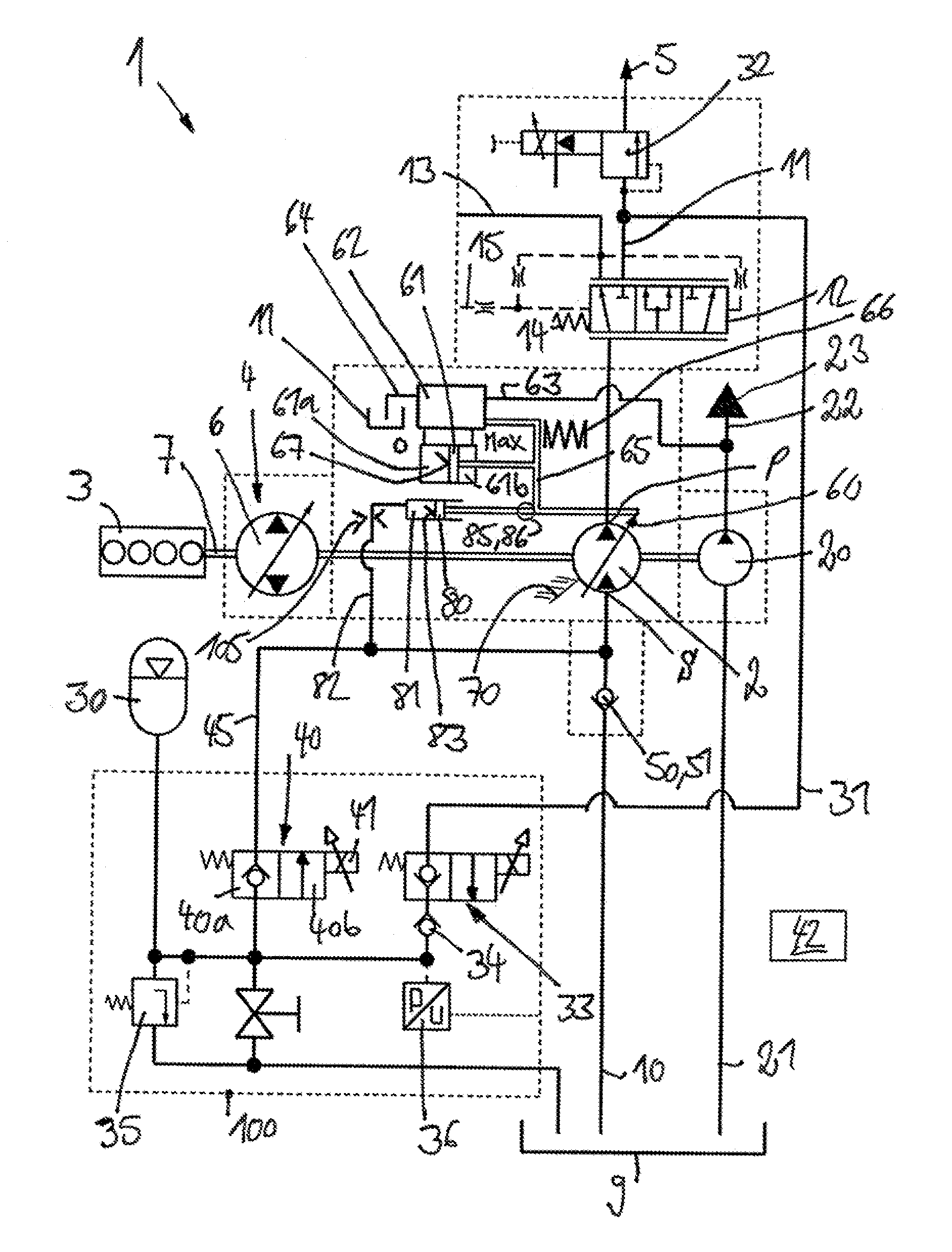
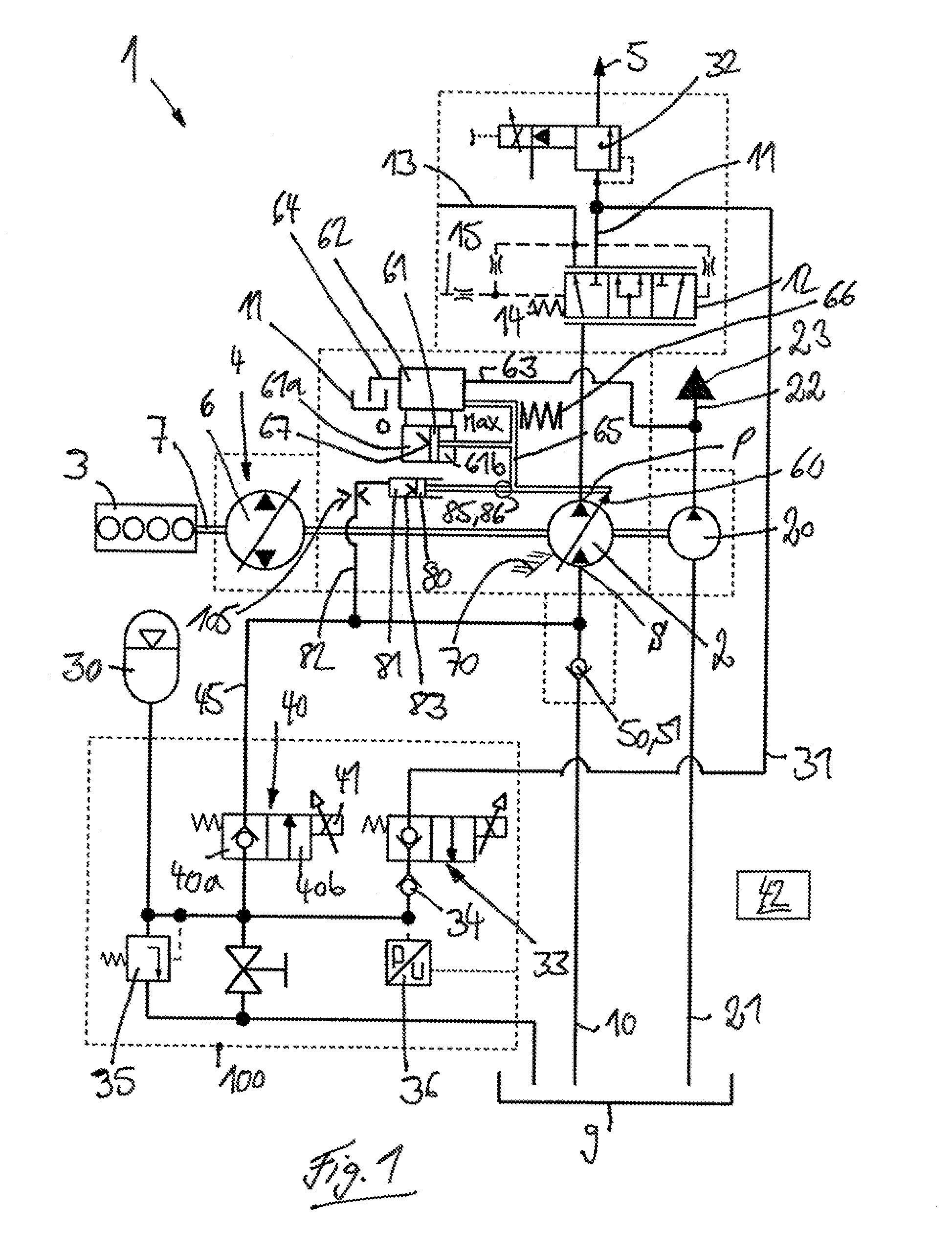
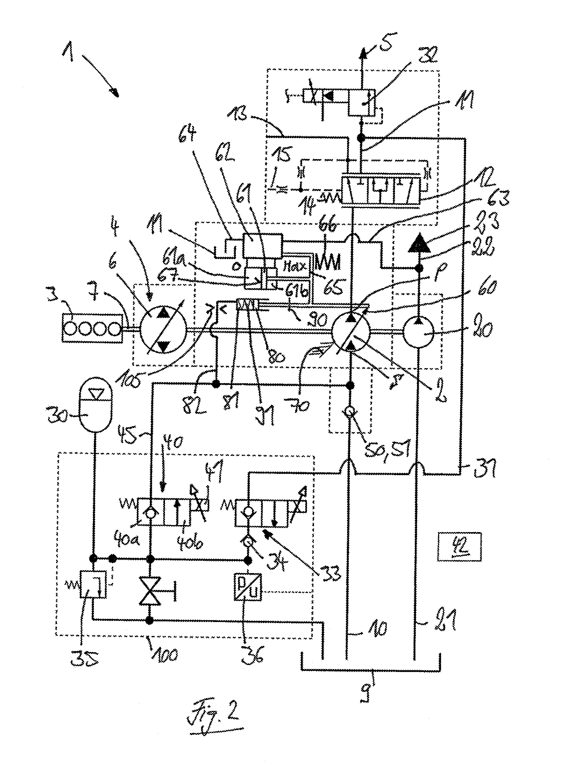
[0040]FIGS. 1-3 show a schematic illustration of a drivetrain 1 of a mobile machine (not illustrated in detail), such as an industrial truck or a piece of construction or agricultural equipment, with a hydrostatic power unit 2 of the invention. The drivetrain 1 includes an internal combustion engine 3, such as a diesel engine, a traction drive 4 driven by the internal combustion engine 3, and the hydrostatic power unit 2 in a drive connection with the internal combustion engine 3. The power unit 2 is a variable displacement machine with a continuously variable displacement volume.

[0041]The illustrated vehicle is also provided with working hydraulics 5 driven by the internal combustion engine 3.

[0042]In the illustrated exemplary embodiment, the traction drive 4 is a hydrostatic traction drive having a variable displacement drive pump 6 driven by a drive connection with an output shaft 7 of the internal combustion engine 3. The drive pump 6 is in communication with one or more constan...


PUM


Abstract

A hydrostatic power unit (2) comprises a variable displacement machine with a continuously variable displacement volume and is operated as a pump and motor and is in a drive connection with an internal combustion engine (3). When operated as a pump, the power unit sucks hydraulic fluid out of a tank (9) and delivers into a delivery side (P), and, when operated as a motor, functions as a hydraulic starter to start the internal combustion engine (3). When operated as a motor, the power unit is supplied with hydraulic fluid from a hydraulic accumulator (30). The displacement volume of the power unit (2) is set by a displacement volume control device (60) actuated by a positioning piston device (61) supplied with hydraulic fluid from a charging pressure circuit (23). The power unit (2) includes a supplemental positioning piston device (80) in an operative connection with the displacement volume control device (60) and which is actuated directly by the pressure present in the hydraulic accumulator (30). By means of a connection of the supplemental positioning piston device (80) with the hydraulic accumulator, the power unit (2) can be adjusted to increase the displacement volume to start the internal combustion engine (3).

Description

CROSS REFERENCE TO RELATED APPLICATIONS[0001]This application claims priority to German Application No. 102013109110.5 filed Aug. 22, 2013, and German Application No. 102013110239.5 filed Sep. 17, 2013, which are herein incorporated by reference in their entirety.BACKGROUND OF THE INVENTION[0002]1. Field of the Invention[0003]This invention relates to a hydrostatic power unit in the form of a variable displacement machine with a variable, in particular a continuously variable, displacement volume and which can be operated as a pump and as a motor and is in a drive connection with an internal combustion engine. When the power unit is operated as a pump, it sucks hydraulic fluid on a suction side from a tank and delivers into a delivery side. When the power unit is operated as a motor, it is a hydraulic starter to start the internal combustion engine. When the power unit is operated as a motor, hydraulic fluid from a hydraulic accumulator is supplied to the suction side of the power u...

Claims


Application Information

Patent Timeline
Patent Type & Authority Applications(United States)
IPC IPC(8): F02N9/04F04B13/00F03C1/26F04B49/12F03C1/00F02B73/00F04B17/05
CPCF02N9/04F02B73/00F04B13/00F03C1/26F04B49/12F03C1/005F04B17/05B60K6/12B60K2006/126F02N7/00F02N11/0814F16H61/42Y02T10/62F02N7/08
Inventor KRITTIAN, LUKASLOEFFLER, THOMASLANGEN, ALFREDLASSAAR, ROLF
Owner LINDE HYDRAULICS
Why Eureka
Try Eureka