Treatment well tiltmeter system

a tiltmeter and wellbore technology, applied in the direction of fluid removal, borehole/well accessories, surveillance, etc., can solve the problems of fractures (cracks, fissures), deformation to the subsurface strata, and complex resultant deformation

Inactive Publication Date: 2006-04-18
HALLIBURTON ENERGY SERVICES INC
View PDF26 Cites 20 Cited by
  • Summary
  • Abstract
  • Description
  • Claims
  • Application Information

AI Technical Summary

Benefits of technology

[0026]The treatment well tiltmeter system comprises one or more tiltmeter assemblies which are located within an active treatment well. The treatment well tiltmeter system provides data from the downhole tiltmeters, which is used to map hydraulic fracture growth or other subsurface processes from the collected downhole tilt data versus time. The system provides data from each of the treatment well tiltmeter assemblies, and provides isolation of data signals from noise associated with the treatment well environment. As well, the treatment well tiltmeter system provides geomechanical modeling for treatment well processes, based upon the treatment well data.

Problems solved by technology

The subsurface injection of pressurized fluid results in a deformation to the subsurface strata.
The resultant deformation may also be more complex, such as in cases where no fracturing is occurring, wherein the subsurface strata (rock layers) compact or swell, due to the poroelastic effects from altering the fluid pressure within the various rock layers.
The pressure created by the fluid is greater than the in situ stress on the rock, so fractures (cracks, fissures) are created.
Surface measurements do not accurately reflect the magnitude and dimensions of a formed fracture, due primarily to the relative isolation of the surface tiltmeters from the fracture area.
However, the prior art systems and methodologies fail to provide tiltmeter assemblies and systems within active wells, nor do they provide structures which can be used in an active well environment.

Method used


Image

  • Treatment well tiltmeter system
  • Treatment well tiltmeter system
  • Treatment well tiltmeter system

Examples


Embodiment Construction

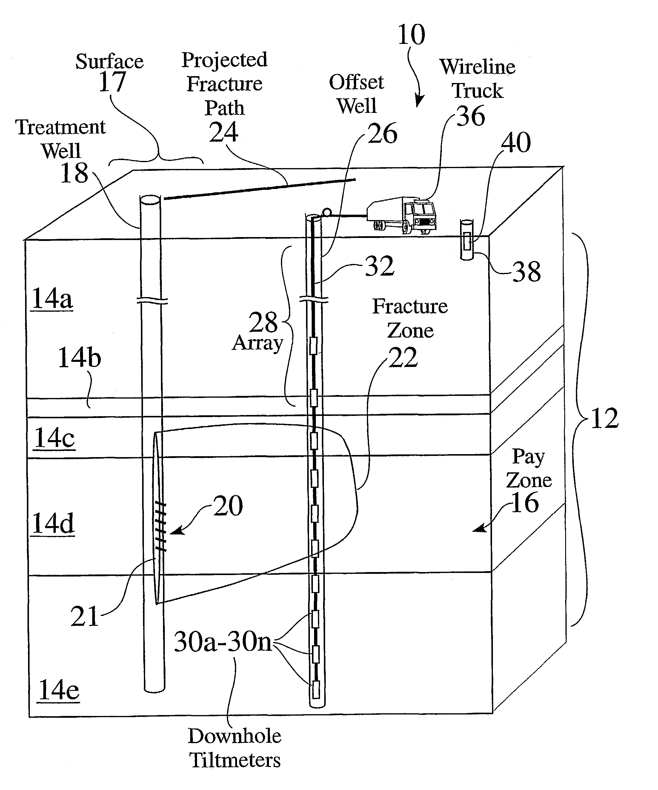
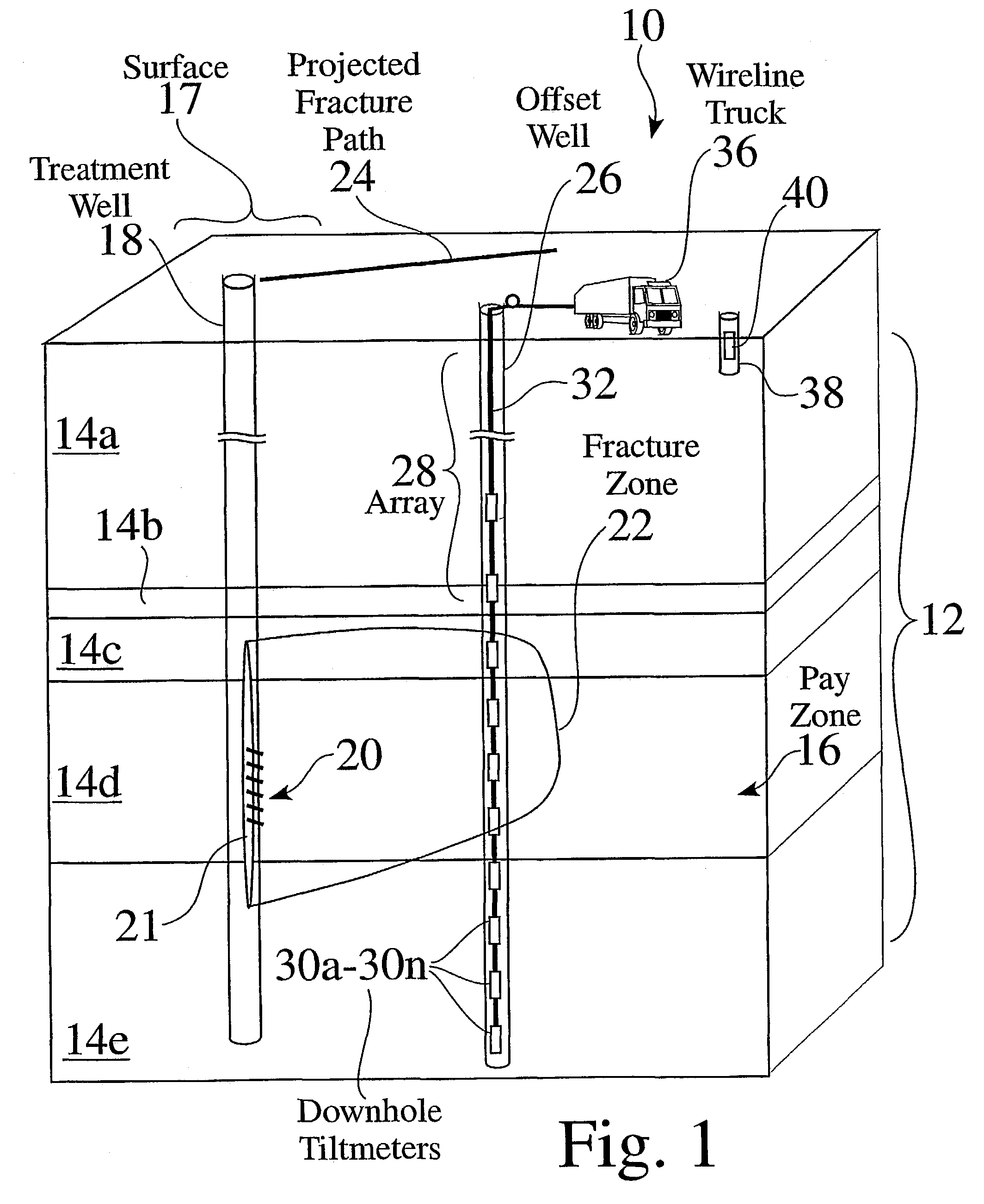
[0170]FIG. 1 is a partial cutaway view 10 showing a treatment well 18 which extends downward into strata 12, through one or more geological layers 14a–14e. A fracture zone 22 is formed within a previously formed perforation region 20 in the treatment well 18, such as to extend into one or more pay zones 16 within the strata 12. A fracture process is typically designed to coincide with a desired projected fracture path 24, such as to extend into a pay zone 16.

[0171]Surface tilt meters 40 are often placed in shallow surface bores 38, to record the tilt of the surface region at one or more locations surrounding the treatment well 18. The surface bores 38 have a typical depth of ten to forty feet. Tilt data collected from the surface tilt meters 40 from a treatment well fracture process is used to estimate the orientation of the formed fracture zone 22.

[0172]As seen in FIG. 1, an array 28 of offset well tilt meters 30a–30n are placed in an offset wellbore 26, to record data from each of...


PUM


Abstract

The treatment well tiltmeter system comprises one or more tiltmeter assemblies which are located within an active treatment well. The treatment well tiltmeter system provides data from the downhole tiltmeters, and can be used to map hydraulic fracture growth or other subsurface processes from the collected downhole tilt data versus time. The system provides tilt data inversion of data from each of the treatment well tiltmeter assemblies, and provides isolation of data signals from noise associated with the treatment well environment. As well, the treatment well tiltmeter system provides geomechanical modeling for treatment well processes.

Description

[0001]This application claims the benefit of provisional application No. 60 / 199,779, file Apr. 26, 2000.FIELD OF THE INVENTION[0002]The invention relates to the field of tiltmeter systems and instrumentation in wellbore systems. More particularly, the invention relates to tiltmeter and instrumentation systems for treatment wells.BACKGROUND OF THE INVENTION[0003]For a variety of applications, fluids are injected into the earth, such as for hydraulic fracture stimulation, waste injection, produced water re-injection, or for enhanced oil recovery processes like water flooding, steam flooding, or CO2 flooding. In other applications, fluids are produced, i.e. removed, from the earth, such as for oil and gas production, geothermal steam production, or for waste clean-up.[0004]Hydraulic fracturing is a worldwide multi-billion dollar industry, and is often used to increase the production of oil or gas from a well. The subsurface injection of pressurized fluid results in a deformation to the...

Claims


Application Information

Patent Timeline
Patent Type & Authority Patents(United States)
IPC IPC(8): E21B47/022E21B43/26E21B47/01E21B47/02E21B49/00
CPCE21B43/26E21B47/01E21B49/008E21B47/022E21B47/02
Inventor WRIGHT, CHRISDAVIS, ERICWARD, JAMESSAMSON, EITIENNEWANG, GANGGRIFFIN, LARRYDEMETRIUS, SHARONFISHER, KEVIN
Owner HALLIBURTON ENERGY SERVICES INC
Why Eureka
Try Eureka