Shoreline erosion barrier

Active Publication Date: 2006-04-18
GRANGER PLASTICS
View PDF26 Cites 51 Cited by
  • Summary
  • Abstract
  • Description
  • Claims
  • Application Information

AI Technical Summary

Benefits of technology

[0008]The present invention provides a barrier for controlling erosion along shorelines. Each barrier is a modular unit that can be arranged together with several other such barriers to form a barrier wall along a shoreline. In one embodiment, the barrier comprises a unitary, molded plastic body with opposing first and second sides and an interior reservoir. At least one elongate passage extends through the barrier body between the first and second sides to permit water to

Problems solved by technology

As a consequence of this persistent wave action, material on the shore tends to be loosened and the continuous reciprocating movement along the shoreline causes such materials to generally erode.
In those situations, devices such as breakwaters and revetments tend to increase downstream erosion.
The dredging process is generally very expensive and serves only as a temporary solution to the problem as the shore is gradually and continually eroded.
Moreover, dredging sand from the floor beneath the body of water creates other environmental concerns such as damage to marine life which inhabit the sea floor.
However, many of these devices do not aid

Method used


Image

  • Shoreline erosion barrier
  • Shoreline erosion barrier
  • Shoreline erosion barrier

Examples


Embodiment Construction

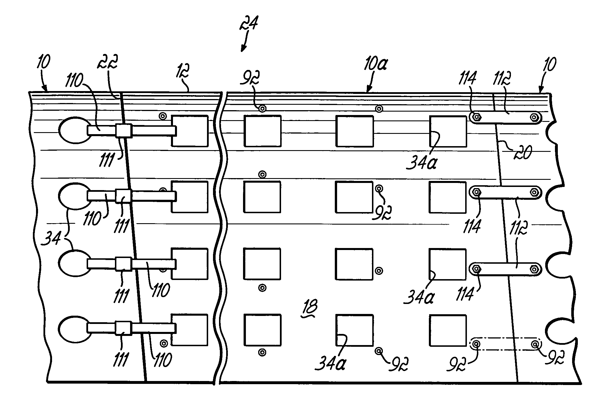
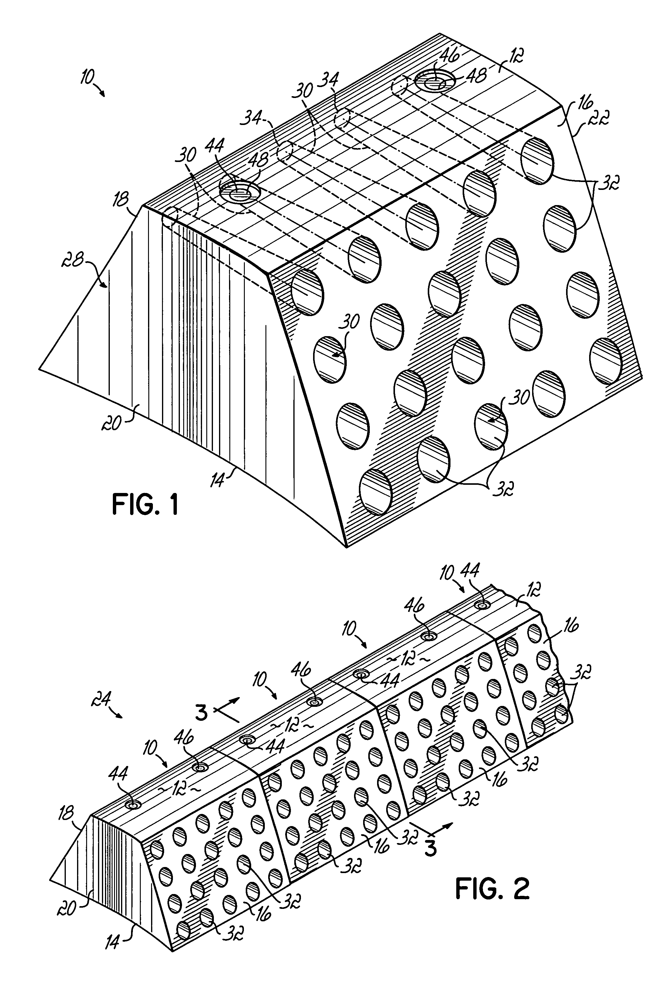
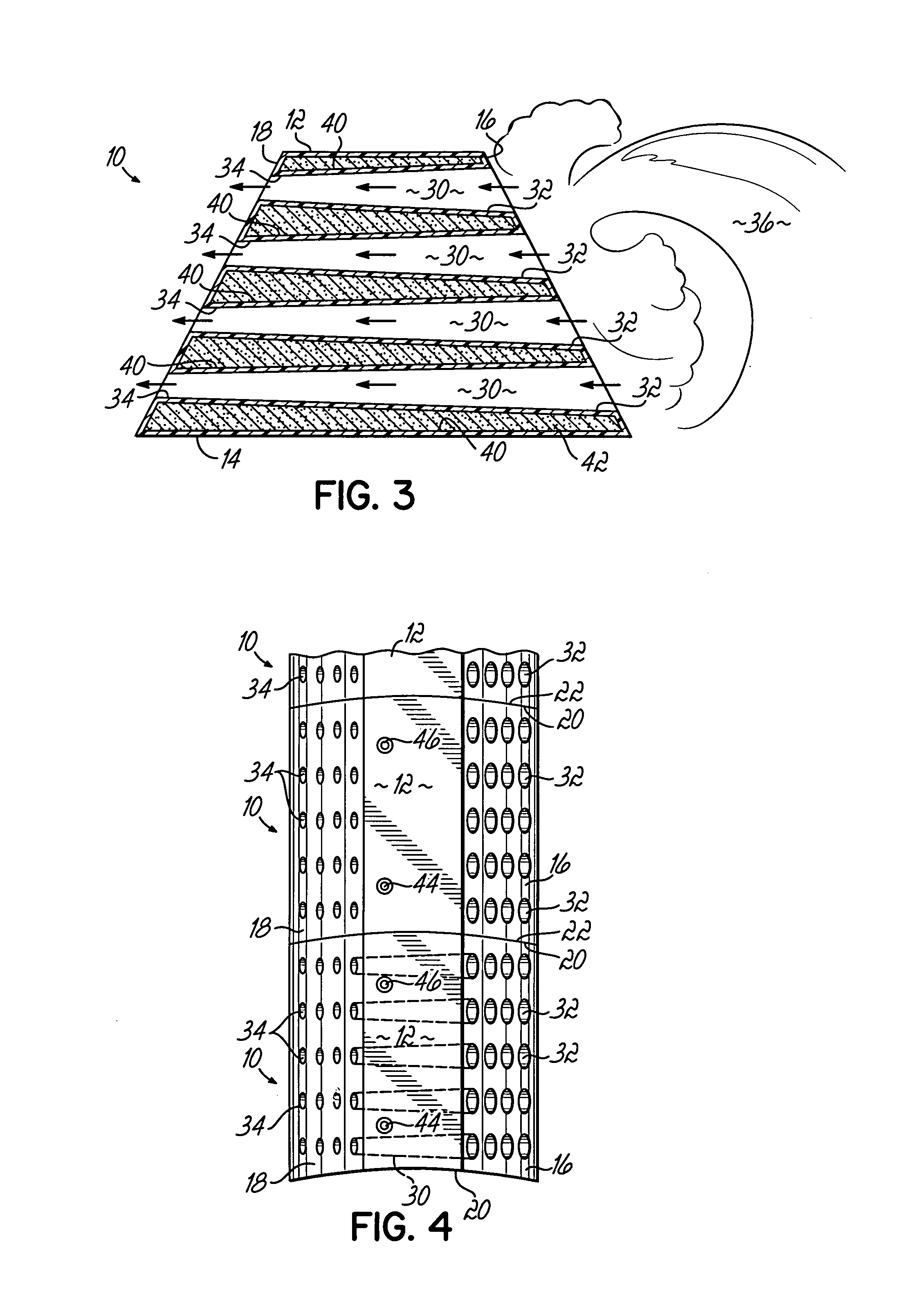
[0021]FIG. 1 depicts an exemplary erosion control barrier 10, according to the present invention. In this embodiment, the barrier has the general shape of a trapezoidal prism with substantially horizontal top and bottom walls 12, 14, first and second opposing, inclined sidewalls 16, 18, and first and second opposing end walls 20, 22. The first and second sidewalls 16, 18 are inclined toward one another, from the bottom wall 14 toward the top wall 12, to form the generally trapezoidal shape. While the first and second end walls 20, 22 are substantially vertically oriented, they are formed as convex and concave arcuate surfaces that extend between the first and second sidewalls 16, 18, respectively. The convex and concave surfaces are complementary so that multiple barriers 10 may be aligned in an end-to-end fashion with their first and second end walls 20, 22 engaging one another to form a barrier wall 24, as depicted in FIGS. 2, 4 and 8, and described more fully below.

[0022]A plural...


PUM


Abstract

A barrier for reducing erosion along shorelines includes a barrier body formed as a unitary, molded plastic structure. In one embodiment, the barrier body has at least one elongate passage extending through it, between oppositely disposed first and second sides, and an interior reservoir. A port formed into the barrier body communicates with the interior reservoir to facilitate filling the reservoir with material to thereby add weight to the barrier. The barrier further includes at least one anchor formed into a side of the barrier body and associated with the passage to control shrinkage of the barrier body as it is being molded. In another embodiment, a method of making the barrier body includes placing plastic material in a mold, manipulating the mold to distribute the plastic material within the mold and thereby form the barrier body as a unitary piece, and reducing the shrinkage of the molded barrier body with the anchor.

Description

CROSS REFERENCE[0001]This application is a continuation of U.S. patent application Ser. No. 10 / 997,226, filed Nov. 24, 2004, now abandoned.FIELD OF THE INVENTION[0002]The present invention relates generally to a device for reducing erosion along shorelines.BACKGROUND OF THE INVENTION[0003]The erosion of shorelines as a consequence of wave action is a well-known phenomenon. Generally, erosion is a function of persistent wave action exerted on beaches comprising sand or fine-shingled material and is most frequently encountered along shorelines of large bodies of water where such wave action can be generated. As a consequence of this persistent wave action, material on the shore tends to be loosened and the continuous reciprocating movement along the shoreline causes such materials to generally erode. The problems of erosion are emphasized along exceptionally long shorelines where the phenomena of littoral drift is enhanced. In those situations, devices such as breakwaters and revetmen...

Claims


Application Information

Patent Timeline
IPC IPC(8): E02B3/04
CPCE02B3/04
Inventor CRAVENS, JAMES
Owner GRANGER PLASTICS
Why Eureka
Try Eureka