
Flameless oxidation burner

a burner and burner technology, applied in the field of burner devices, to achieve the effect of more versatile us

Inactive Publication Date: 2006-04-18
WS WARMEPROZESSTECHN
View PDF34 Cites 15 Cited by
  • Summary
  • Abstract
  • Description
  • Claims
  • Application Information

AI Technical Summary

Benefits of technology

[0005]It is an object of the present invention to provide a burner device for flameless oxidation of fuels which is suitable for more versatile usage.
[0008]The fuel and air are directed essentially without spin, spreading out in individual jets in the vicinity of the fuel head. It has been shown that these jets are not pulled along or significantly disrupted by an exhaust jet flowing transversely in the vicinity of the jets into the exhaust channel. This can be accomplished by designing or setting the cross sectional outlets for the flows of the fuel-air mixture and of the exhaust jet so that they have very different properties. For relatively high fuel and / or air speed, a comparatively much lower exhaust speed is produced. The fuel-air jet can thus entrain, mix with, and react with parts of the slower exhaust jet without producing flames. The exhaust channel, whose inlet opening is arranged in the vicinity of the burner head, also can be designed so that the fuel-air jet is deflected towards and contacts the wall.
[0009]The inlet opening of the exhaust channel can be arranged around the burner head. While the inlet opening of the exhaust channel ends at the wall, the burner head projects somewhat into the reaction chamber. Thus, the jets of the burner-air mixture cross the inlet openings of the exhaust channel in front of the wall. The inlet opening can be divided, if necessary, into several partial openings. For example, it is possible to provide screens in the inlet opening, which further reduce the exhaust speed in the vicinity of the outlet openings of the burner head.
[0010]The burner head preferably is formed so that the fuel-air mixture from the outlet opening is at a speed sufficient for flushing away any possible flames. This enables flameless operation in which the reaction of fuel and air is distributed over a greater part of the reaction chamber. In addition, the fuel-air jet suctions and entrains considerable exhaust gas in the vicinity of the inlet opening of the exhaust gas channel, which further supports the flameless operation.
[0011]The burner preferably contains means, such as a recuperator or a regenerator, for pre-heating the fuel, the air, or the fuel-air mixture. This further results in good energy usage and supports the formation of flameless oxidation.
[0012]Preferably, the burner is provided with means for switching between a first and a second operating modes, wherein in the first operating mode a flame is formed partially within the burner head. This operating mode can be used for pre-heating. Local overheating of the reaction chamber is prevented because the flame extends only partially from the burner head. After the warm-up period, the burner can be switched into a second operating mode. This prevents overheating of parts of the reaction chamber or the burner head due to the reaction being distributed over a large area. The switching between operating modes can be realized by changing the supply of fuel, by changing the air or gas speeds, or by adjusting flame retention baffles arranged in the interior chamber of the burner head.

Problems solved by technology

However, there is often the desire to also heat such furnace chambers with burners operating without flames even when objects are located in front of the burner or if the burners cannot be operated with an axial fuel outlet for other reasons.
However, since these burners do not operate with flameless oxidation the known disadvantages of such burners, such as the formation of local, very hot zones and a high production of nitrogen oxides must be taken into account.

Method used


Image

  • Flameless oxidation burner
  • Flameless oxidation burner
  • Flameless oxidation burner

Examples


Embodiment Construction

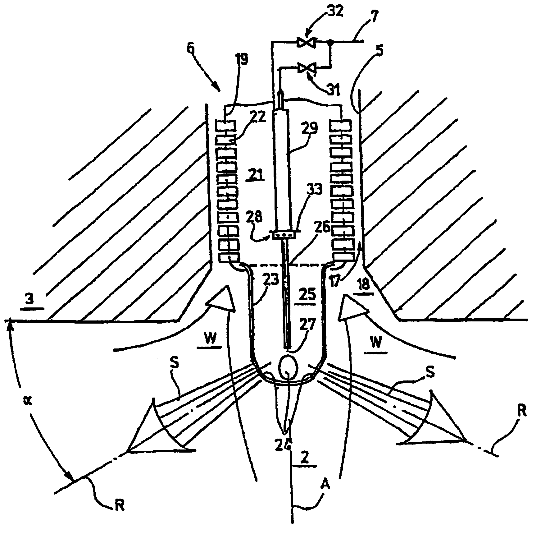
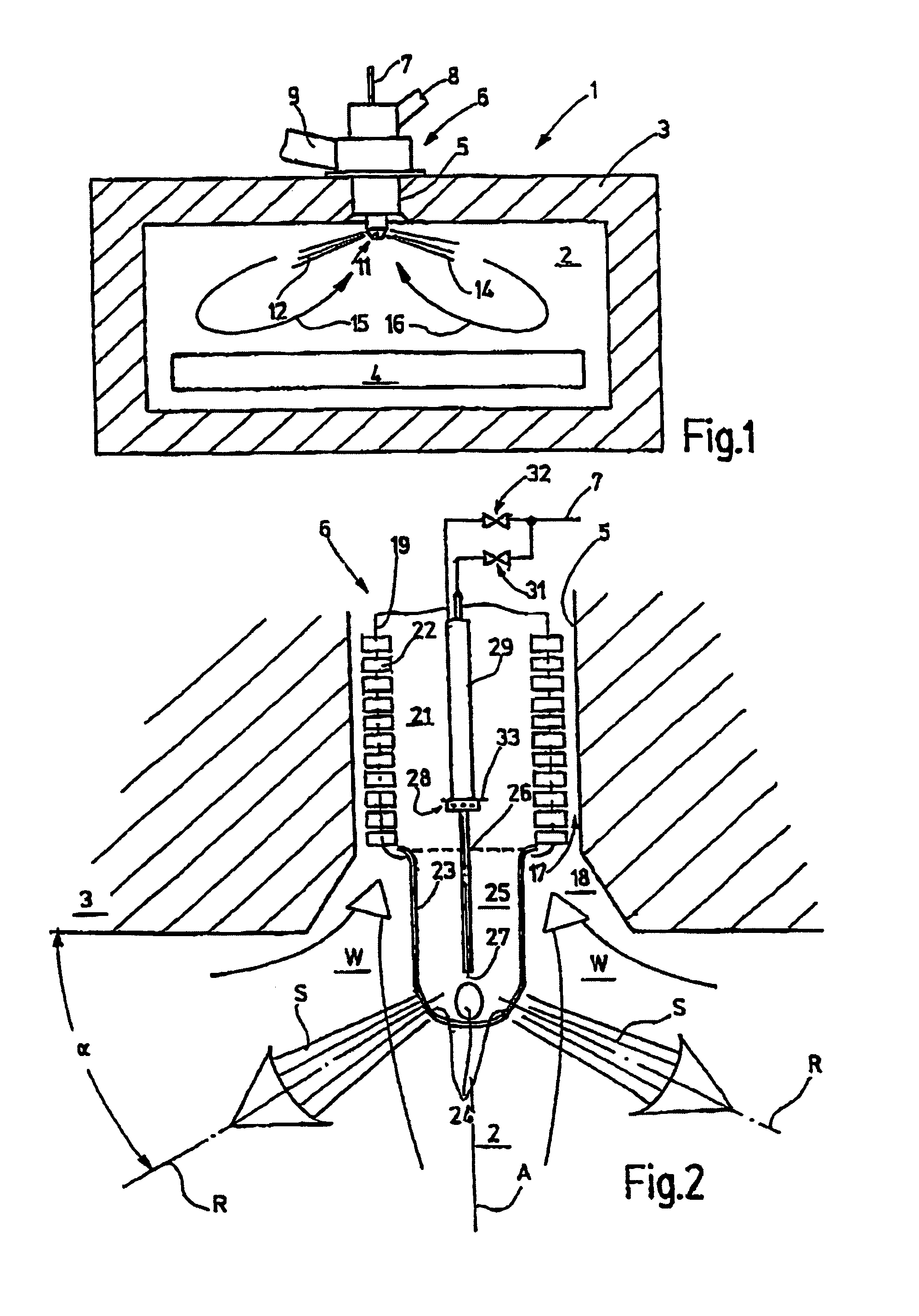
[0021]Referring now more particularly to the drawings, there is shown an illustrative furnace 1 in accordance with the invention. The furnace 1 in this case includes a furnace wall 3 in adjacent relation to a furnace reaction chamber 2 and is operable for heating an object or article 4 disposed within the chamber 2. The illustrated furnace wall 3 has a through hole 5 disposed above the object 4 to be heated, which extends in perpendicular relation to the wall 3. A burner 6 arranged in the through hole 5 is connected to a fuel line 7, an air-supply line 8, and an exhaust gas line 9. The burner 6 projects inwardly past the furnace wall 3 and has a burner head 11, which blows one or more jets 12, 14 of fuel-air mixture into the furnace chamber 2 to produce a large-area circulation, which is illustrated in FIG. 1 by arrows 15, 16.

[0022]The burner 6, as depicted in FIG. 2, includes an exhaust gas channel 17 defined externally by the wall of the through hole 5 which can be provided with a...


PUM


Abstract

A device including a burner (6) for directing a fuel / air mixture into a reaction chamber (2) for flameless oxidation of fuels. The burner (6) discharges a fuel / air jet transversely to a longitudinal axis (A) of the burner and an exhaust gas channel (17) is arranged in or on the burner concentric or parallel to the burner longitudinal axis (A). An outlet direction (R) of the fuel / air jets from the burner and the direction (A) of the exhaust gas channel cross each other. Hence, the burner introduces fuel parallel or at an angle to the wall into the furnace chamber where the burner is mounted for flameless oxidation of the fuel.

Description

FIELD OF THE INVENTION[0001]The present invention relates generally to heating burner devices, and more particularly to a burner device for the flameless oxidation of fuels.BACKGROUND OF THE FILED OF THE INVENTION[0002]The heating of furnace chambers with burners, which are designed for flameless oxidation of fuel within the furnace chamber, is known in the art. Burners which heat a furnace chamber by means of flameless oxidation have significant advantages for many applications over burners that form flames. The heat generation can be distributed over a large area of the furnace chamber and the formation of nitrogen oxides is low.[0003]Flameless oxidation, as well as a furnace suitable for this process, disclosed in EP 0463218 B1. The furnace includes a furnace chamber with walls in which one or more burners are arranged. Fuel and air are introduced into the furnace chamber by means of the burners and exhaust gas is discharged. The burners generate a fuel / air mixture which is injec...

Claims


Application Information

Patent Timeline
Patent Type & Authority Patents(United States)
IPC IPC(8): F23D11/44F23C9/00F23L15/02F23L15/04
CPCF23C9/006F23L15/02F23L15/04F23C2900/03005Y02E20/342F23C2900/99001Y02E20/34
Inventor WUNNING, JOACHIM G.WUNNING, JOACHIM A.
Owner WS WARMEPROZESSTECHN
Learn More