Ablation system and method of use

a technology of ablation system and ablation device, which is applied in the direction of catheters, surgical forceps, therapy, etc., can solve the problems of quite complex surgical maze procedures, and achieve the effect of reducing increasing the power of applied ablation energy

Inactive Publication Date: 2006-04-18
MEDTRONIC INC
View PDF26 Cites 125 Cited by
  • Summary
  • Abstract
  • Description
  • Claims
  • Application Information

AI Technical Summary

Benefits of technology

[0009]Following onset of application of ablation energy to heart tissue, the amplitude of a local electrogram measured with electrodes located adjacent tissue to be ablated first gradually drops and then stabilizes, indicating that the tissue being monitored has ceased making any contribution to the sensed electrogram. The amplitude drop (ΔEGM) or the following amplitude plateau “P” may be used alone or together as indicators of transmurality employed by the present invention. The amplitude drop may be compared to a pre-set value (ΔEGM? a). (The plateau “P” may be detected in response to a determination that the rate of amplitude change is less than a defined value over a series of amplitude measurements or over a defined duration (|dA/dt|=b). In some embodiments, detection of a rapid drop in amplitude (dA/dt=d) may be employed as an indicator that the ablation process is proceeding too quickly and may be employed to trigger a reduction in the power of applied ablation energy. In other embodiments, detection of an insufficiently rapid drop in amplitude (dA/dt=d) may be employed as an indicator that the ablation

Problems solved by technology

Although successful in treating AF, the surgical Maze procedure is quite complex and is currently perform

Method used


Image

  • Ablation system and method of use
  • Ablation system and method of use
  • Ablation system and method of use

Examples


first embodiment

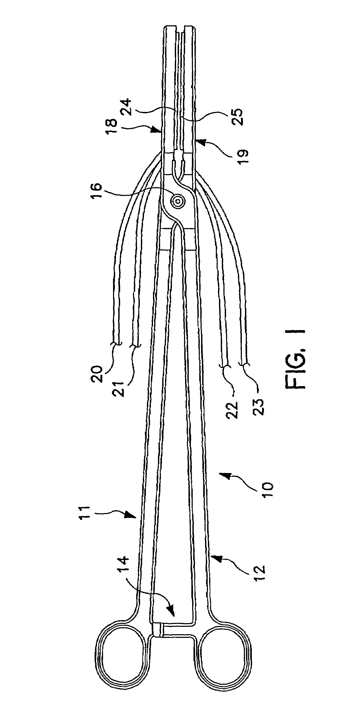
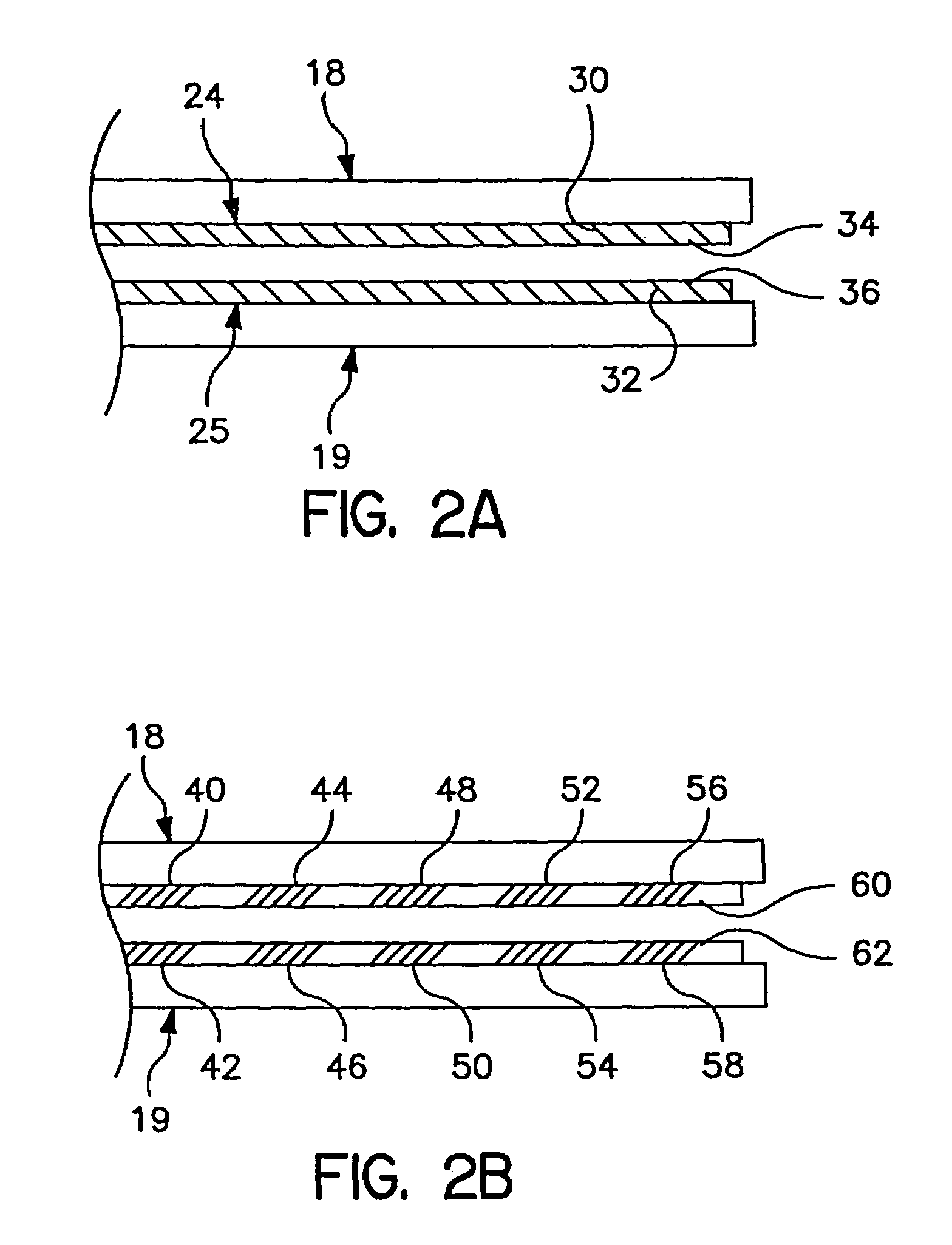
[0024]FIG. 2a shows an electrode arrangement for a hemostat generally as illustrated in FIG. 1. Illustrated components correspond to identically numbered components in FIG. 1. In this embodiment, electrodes 24 and 25 take the form of elongated coil electrodes 30 and 32, mounted around porous tubes 34 and 36, through which saline or other conductive fluid is delivered. The arrangement of the electrodes may also be reversed, for example placing coils 30 and 32 within elongated porous tubes 34 and 36, to accomplish a similar result. Alternatively, any other arrangement for providing an elongated electrode and delivery of saline solution along the length thereof may be substituted. The particular configuration of the electrode is not critical to the present invention. For example, irrigated electrodes corresponding to those described in U.S. Pat. No. 6,096,037 issued to Mulier, et al., U.S. Pat. No. 5,876,398 issued to Mulier, et al., U.S. Pat. No. 6,017,378 issued to Brucker, et al or ...

second embodiment

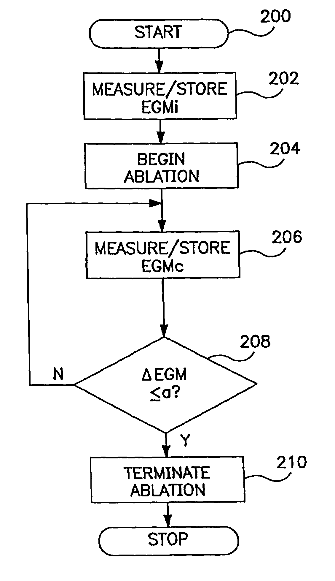
[0039]FIG. 6 is a functional flow chart illustrating the operation of a device as in FIG. 4, according to the present invention. The flow chart of FIG. 6 illustrates operation of the device of FIG. 4 to control provision of R-F energy to an individual electrode or electrode pair. In the event that multiple electrodes or electrode pairs are employed, the control methodology of FIG. 6 would be applied to each electrode or electrode pair individually, as discussed in more detail below in conjunction with FIGS. 10 and 11.

[0040]The flow chart of FIG. 6 illustrates a method of assessing transmurality and terminating delivery of ablation energy to an electrode or an electrode pair responsive to detection of a specified drop in electrogram amplitude, e.g. a 75% drop in conjunction with detection of an electrogram amplitude plateau. Following the detection of the required amplitude drop and plateau, the device may wait a defined time period to assure completion of the lesion and then termina...


PUM


Abstract

A system and method for creating lesions and assessing their completeness or transmurality. Assessment of transmurality of a lesion is accomplished by monitoring the depolarization signal in a local electrogram taken using electrodes located adjacent the tissue to be ablated. Following onset of application of ablation energy to heart tissue, the local electrogram is measured with electrodes located adjacent tissue to be ablated so that the ablation energy to ablation elements can be selectively reduced or terminated when transmurality is detected.

Description

RELATED US APPLICATION DATA[0001]This application is a continuation of U.S. Ser. No. 10 / 132,392, filed Apr. 24, 2002 by Francischelli et al, now U.S. Pat. No. 6,663,627, and also claims priority to Provisional U.S. Patent Application No. 60 / 286,923, filed Apr. 26, 2001 by Francischelli et al., incorporated herein by reference in its entirety.BACKGROUND OF THE INVENTION[0002]The present invention relates to tissue ablation devices generally and relates more particularly to devices adapted to ablate lines of tissue, for example for use in conjunction with an electrosurgical version of the Maze procedure.[0003]The Maze procedure is a surgical intervention for patients with chronic atrial fibrillation (AF) that is resistant to other medical treatments. The operation employs incisions in the right and left atria which divide the atria into electrically isolated portions which in turn results in an orderly passage of the depolarization wave front from the sino-atrial node (SA Node) to the...

Claims


Application Information

Patent Timeline
IPC IPC(8): A61B18/18A61B5/02A61N1/00A61B5/04A61B18/12A61B18/14A61N1/40
CPCA61B5/04A61N1/403A61B18/1445A61B18/12A61B2018/00065A61B2018/00363A61B2018/00577A61B2018/00654A61B2018/00702A61B2018/00755A61B2018/00779A61B2018/00791A61B2018/00839A61B2018/00875A61B2018/1226A61B2018/1253A61B2018/126A61B2018/1467A61B2018/1472A61B2218/002A61B5/24
Inventor FRANCISCHELLI, DAVID E.WARMAN, EDUARDO N.MEHRA, RAHULSTEWART, MARK T.SKARDA, JAMES R.PURYEAR, HARRYSCHWARTZMAN, DAVID
Owner MEDTRONIC INC
Why Eureka
Try Eureka