Method to reduce particle level for dry-etch

a dry-etching and particle technology, applied in the field of semiconductor device manufacturing, can solve the problems of reducing intensity, erroneous end-point signals, and accumulating residues on the surface inside the plasma treatment chamber, so as to prolong the lifetime of inductively coupled plasma, reduce applied power, and reduce particle count

Inactive Publication Date: 2008-06-03
TAIWAN SEMICON MFG CO LTD
View PDF6 Cites 5 Cited by
  • Summary
  • Abstract
  • Description
  • Claims
  • Application Information

AI Technical Summary

Benefits of technology

[0022]It is the primary objective of the invention to provide a method of reducing particle count within the dry-etch chamber at the end of the dry-etch chamber cleaning process.
[0023]Another objective of the present invention is to reduce the need for cleaning of the dry-etch chamber.
[0024]Yet another objective of the present invention is to prolong the lifetime of Inductively Coupled Plasma (ICP) or any other type of High Density Plasma (HDP) dry-etch processing kits.
[0025]In accordance with the objectives of the invention, the invention teaches a multi-step method of reducing applied power during the process of cleaning the dry-etch chamber. The ICP rf power (that is used to agitate the wall polymer or other residual reaction products within the dry-etch chamber) is reduced between each of these consecutive power-down steps of the cleaning of the dry-etch chamber.

Problems solved by technology

Such etching, however, results in residues or deposits building up on surfaces inside the plasma treatment chamber.
If however the window through which the endpoint monitoring takes place becomes layered with adhering RIE products, the endpoint detection signal will decrease in intensity which can at times result in erroneous end-point signals.
A build-up of these residues deteriorates the etch performance of the dry-etch.
As such, the presence of such residues is undesirable.
Using current one-step cleaning procedures results in a violent transition of the plasma in going from the operating condition of rf-on to rf-off.
This results in uncontrolled particle levels within the dry-etch chamber, a condition that is very detrimental to the proper operation and control of the dry-etch process.
Using the indicated process, the particle count of the wall polymer or other residual reaction products 12 within the chamber is difficult to control while the particle level is unstable.

Method used


Image

  • Method to reduce particle level for dry-etch
  • Method to reduce particle level for dry-etch
  • Method to reduce particle level for dry-etch

Examples


Embodiment Construction

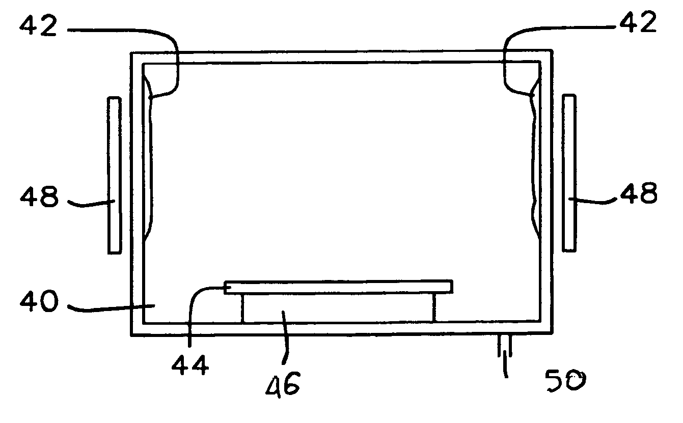
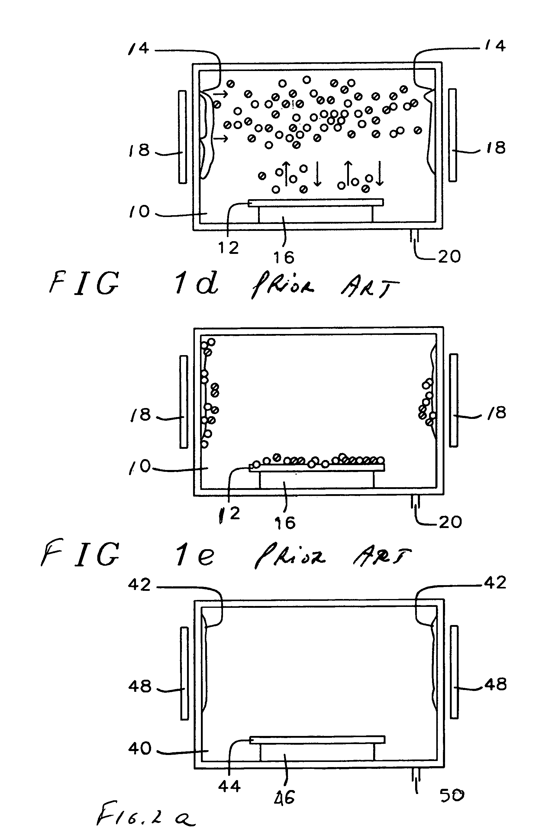
[0043]Referring now specifically to FIG. 2, there is shown the cleaning process of the invention as applied to a (photolithography) mask. FIG. 2a shows the dry-clean chamber 40, a wall polymer or other residual reaction product 42 and the mask 44 that is positioned on a table 46. A rf coil 48 is provided around and on the outside of the chamber 40, the rf coil provides the electrical energy to the polymer 42. The polymer, as a consequence of the energy provided by the ICP coil 48, evaporates inside the dry-etch chamber 40. Excess of wall polymer or other residual reaction product is removed via the suction pump 50.

[0044]FIG. 2b shows the wall polymer or other residual reaction product molecules 52 being distributed throughout the chamber after the rf coil ICP 48 has been activated and the RIE etch has been started.

[0045]FIG. 2b represents the first step of the power-down sequence of the dry-etch process. This first step is out of a total of six dry-etch power-down steps within the s...


PUM

PropertyMeasurementUnit
rf poweraaaaaaaaaa
rf poweraaaaaaaaaa
rf poweraaaaaaaaaa

Abstract

The invention teaches a multi-step method for shutting down the dry-etch process. The ICP rf power is reduced between each of these consecutive power-down steps of the dry-etch process, the complete power-down sequence consists of six steps. These six steps are executed in sequence and without interruption and form the totality of the dry-etch chamber power-down procedure.

Description

BACKGROUND OF THE INVENTION[0001](1) Field of the Invention[0002]The invention relates to the field of semiconductor manufacturing, and more specifically to a method to reduce the dry-etch chamber particle level during the power-down procedure of the dry-etch cleaning process for lithography masks.[0003](2) Description of the Prior Art[0004]The trend within the semiconductor manufacturing industry to micro-miniaturization and the ability to produce chips with sub-micron features has resulted in a continuous increase of the performance of semiconductor chips while at the same time the cost of semiconductor chips has continued to decrease.[0005]Micro-miniaturization of semiconductor chips has been achieved by significant advances in specific semiconductor fabrication disciplines such as photolithography and dry-etching. Sub-micron features in photo-resist layers have been routinely achieved by the use of more sophisticated exposure cameras, as well as by the use of more sensitive phot...

Claims


Application Information

Patent Timeline
Patent Type & Authority Patents(United States)
IPC IPC(8): B44C1/22
CPCH01J37/321H01J37/32862Y10S438/905
Inventor CHIN, SHENG-CHILIN, SHY-JAY
Owner TAIWAN SEMICON MFG CO LTD
Why Eureka
Try Eureka