
Method and device for dispensing adhesive laminate segments

Inactive Publication Date: 2006-04-18
LTS LOHMANN THERAPIE-SYST AG
View PDF12 Cites 28 Cited by
  • Summary
  • Abstract
  • Description
  • Claims
  • Application Information

AI Technical Summary

Benefits of technology

[0015]Since, especially in the case of successive detachment, only a fraction of the pressure-sensitive adhesive force needs to be overcome at a time, it is also possible in the process according to the invention to make use of the measure of guiding the primary carrier band at a slower transport rate relative to the secondary carrier band. This enables, for instance, the late placement, or adhesion, of a pressure-sensitive adhesive laminate section onto the secondary band, with only a small portion still sticking to the primary carrier web. In this way, it is possible to realise substantial differences in band speed between the primary and secondary bands, thereby enabling an increase in the distances between the individual systems without taking further measures. The dispensing process may be accomplished in continuous or intermittent operation.

Problems solved by technology

With this kind of fabrication of dermal or transdermal therapeutic, pressure-sensitive adhesive laminate sections, the surface coating of the carrier band may become damaged upon punching through the matrix and a backing layer connected with the matrix, which in the case of prolonged storage will cause problems in releasing the matrix from the carrier layer, especially where the therapeutic system possesses a strong tendency for cold flow, enabling the matrix to unintentionally form a pressure-sensitive adhesive bond with the carrier layer, which carrier layer has not been rendered adhesive.
If, however, the adhesive force of the matrix exceeds a certain value, this method can no longer be applied as the pressure-sensitive adhesive matrix in this case is no longer detachable from the carrier band but is deflected along with the primary carrier band.
If the adhesion of the plaster to the primary carrier layer is very strong, this may, even in the case of a very acute dispensing angle, cause the plaster to be pulled around the edge along with the primary carrier layer without becoming detached therefrom, thus making a dispensing process impossible.

Method used


Image

  • Method and device for dispensing adhesive laminate segments
  • Method and device for dispensing adhesive laminate segments
  • Method and device for dispensing adhesive laminate segments

Examples


Embodiment Construction

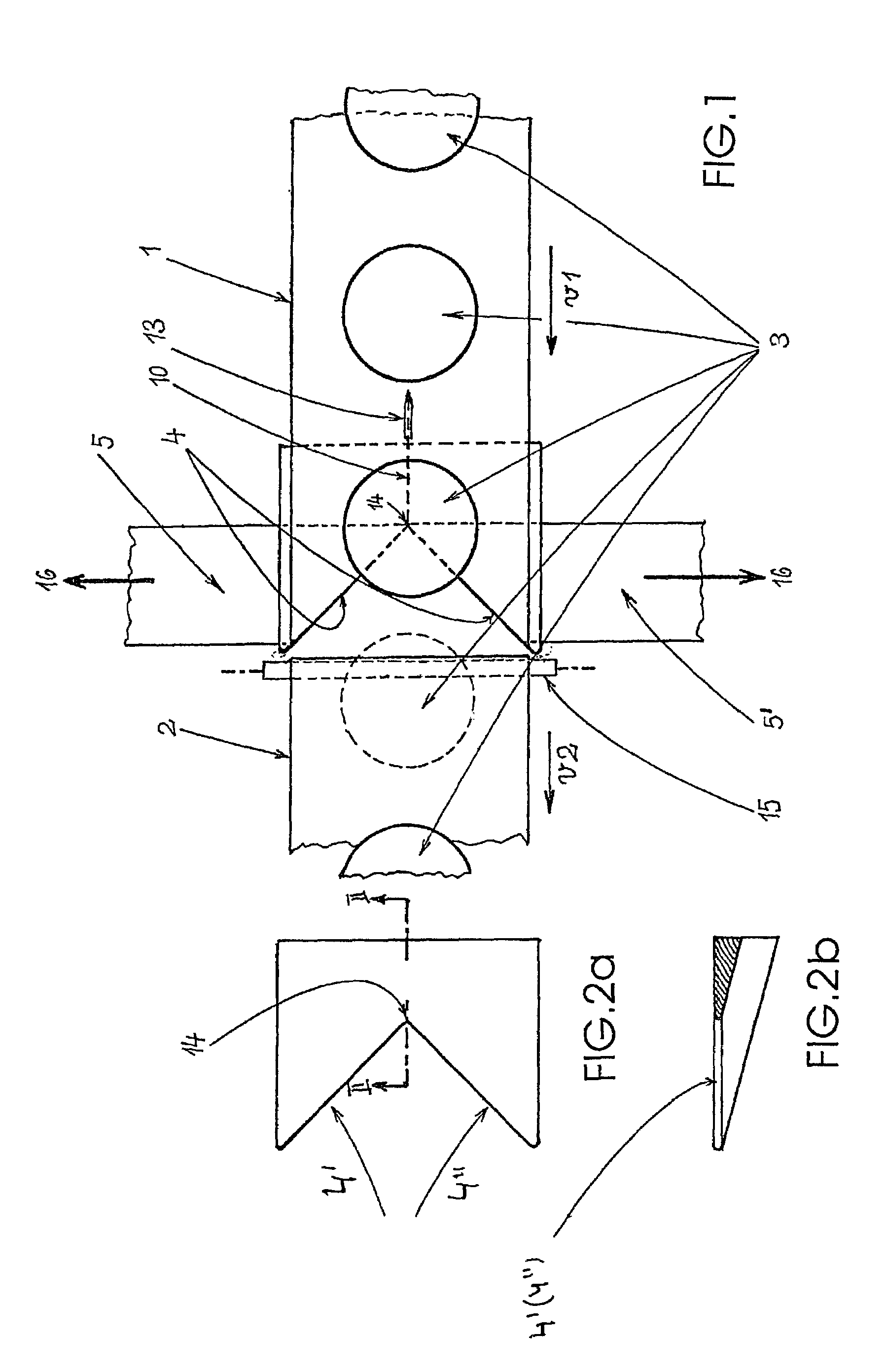
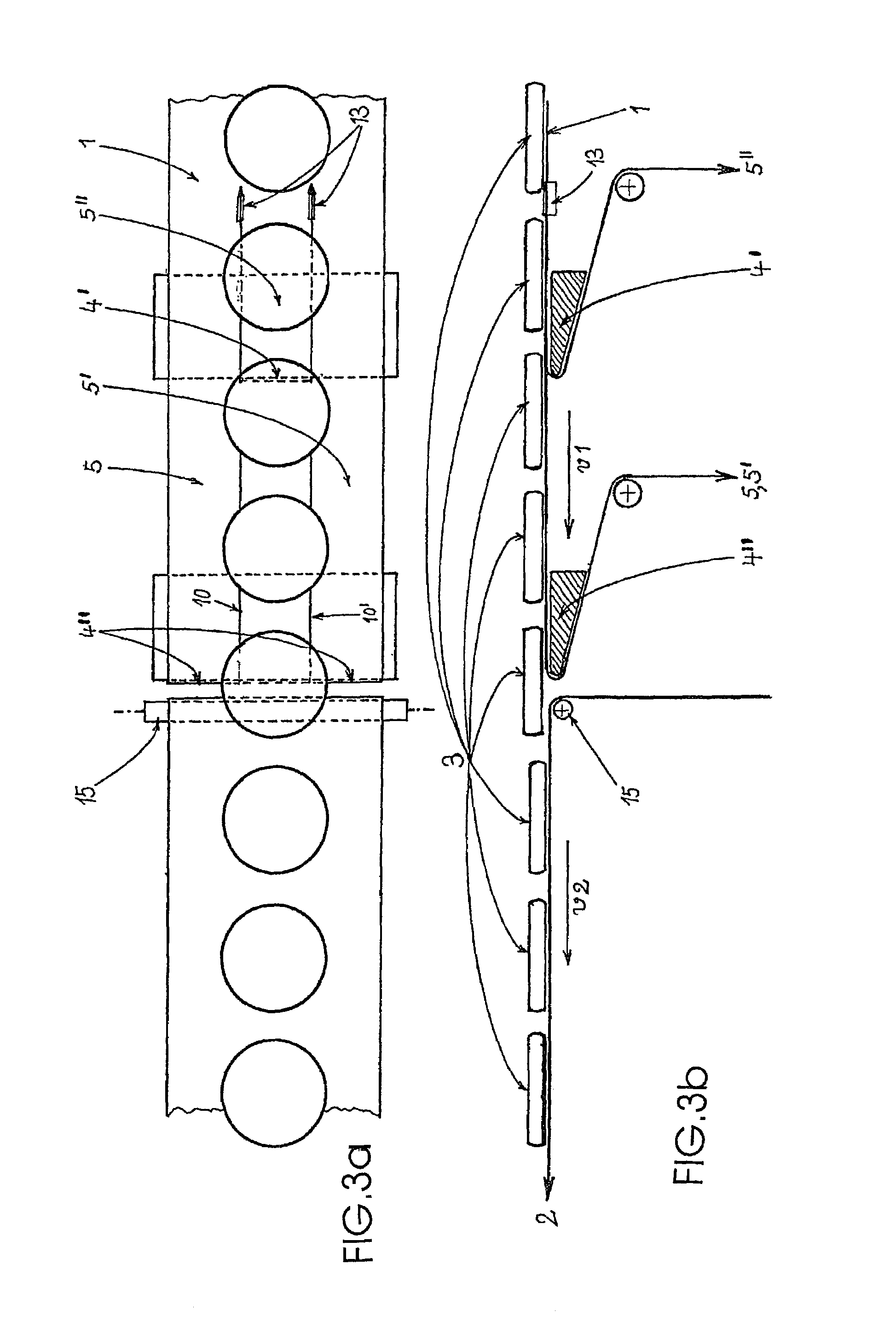
[0026]The process for dispensing pressure-sensitive adhesive laminates 3 or laminate sections from a movable primary carrier band 1 to a movable secondary carrier band 2, with the laminates 3, upon deflection of the primary band 1 around a dispenser edge 4, being detached and being dispensed onto the secondary band 2, will become clear from viewing the FIGS. 1 to 3b together and is characterized by the fact that the primary band 1 is divided into at least two strips 5, 5′, the strips are deflected individually at the dispenser edge 4 and the laminates 3 are, in the process, removed from the strips 5, 5′ and dispensed onto the secondary band 2.

[0027]This secondary band 2 can be advanced from underneath the band towards the discharge side of the primary band 1 via at least one deflecting roll 15.

[0028]As can be seen from FIG. 1, the band velocities V1 and V2, may be different, that is, V2 can be moved more slowly or more rapidly than V1. The distances between the laminate sections 3, ...


PUM

PropertyMeasurementUnit
Angleaaaaaaaaaa
Angleaaaaaaaaaa
Angleaaaaaaaaaa

Abstract

A process for dispensing pressure-sensitive adhesive laminates (3) or laminate sections from a movable primary (1) onto a movable secondary carrier band (2), the laminates (3), upon deflection of the primary band (1) around a dispenser edge (4), being detached and dispensed onto the secondary band (2), is characterized in that the primary band (1) is provided with at least one separation line or predetermined breaking line, thus subdividing it into at least two strips (5, 5′), and that the strips are individually drawn from separate sections (4′, 4″) of the dispenser edge (4).

Description

BACKGROUND OF THE INVENTION[0001]1. Field of the Invention[0002]Process and device for dispensing pressure-sensitive adhesive laminate sections from a movable primary onto a movable secondary carrier band.[0003]2. Description of the Related Art[0004]The invention relates to a process for dispensing pressure-sensitive adhesive laminates or laminate sections from a movable primary to a movable secondary carrier band, said laminates, upon deflection of the primary band around a dispenser edge, being detached and dispensed onto the secondary band.[0005]It is known how to produce and use pressure-sensitive adhesive laminate sections which are adhesive over a surface. These may be, for example, labels, stickers, transdermal therapeutic systems (TTSs) or double-sided adhesive tape. The pressure-sensitive adhesive surface or a pressure sensitive adhesive-rendered matrix of these laminate sections is typically covered by a carrier band at least partially projecting beyond the same. Technical...

Claims


Application Information

Patent Timeline
IPC IPC(8): B44C1/00B65G59/00A61F13/02A61K9/70A61L15/44C09J7/02
CPCA61F13/0276A61K9/7023B65H37/002B65H35/02A61F2013/0296Y10T156/1085Y10T156/1705Y10T156/1348
Inventor VON FALKENHAUSEN, CHRISTIANSCHUMANN, KLAUSSTEINBORN, PETERTHEOBALD, FRANK
Owner LTS LOHMANN THERAPIE-SYST AG
Learn More