
System for solid-liquid separation

a solid-liquid separation and system technology, applied in the direction of filtration separation, separation process, moving filter element filter, etc., can solve the problems of reliability, leakage, costlier equipment, etc., and achieve the effect of less structural strength, easy design and construction, and less leakag

Inactive Publication Date: 2006-04-18
TAPP FLOYD G
View PDF19 Cites 18 Cited by
  • Summary
  • Abstract
  • Description
  • Claims
  • Application Information

AI Technical Summary

Benefits of technology

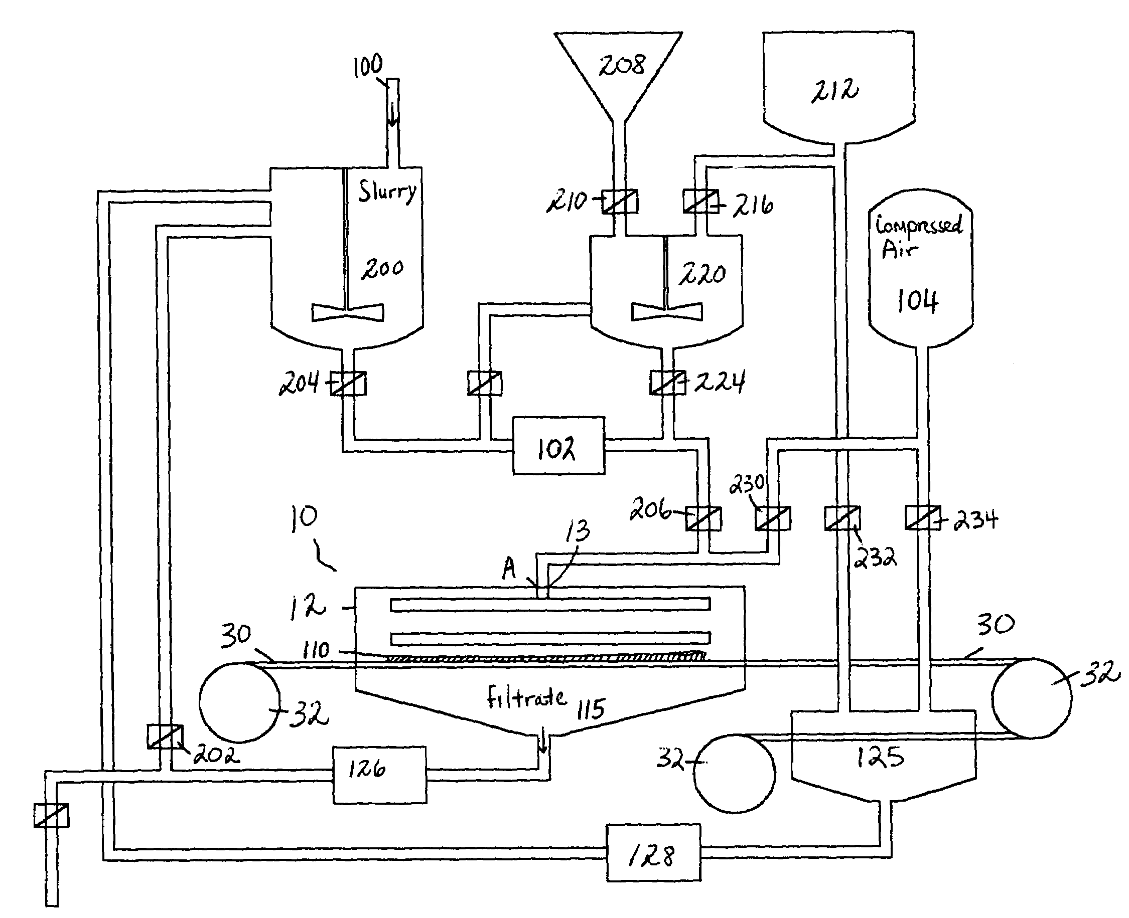
[0010]More throughput for less cost while meeting industry “dry” solids standards is the principal objective of the present invention. Poiseuille's Law as applied to filter cakes confirms that the higher the pressure the faster the liquid flows through the filter cake. The present invention uses air pressure to squeeze the filter cake and dewater it. Air pressure is the optimum method for dewatering a uniformly distributed cake. It is more troublefree than methods using membranes or diaphragms and air moving through the cake helps to produce a substantially dry cake.
[0011]The design of the present invention allows the operator to adjust both the time intervals and amount of pressure for the cake buildup and for the cake dewatering. These variables are adjusted to optimize the dewatering cycle for maximum throughput per hour.
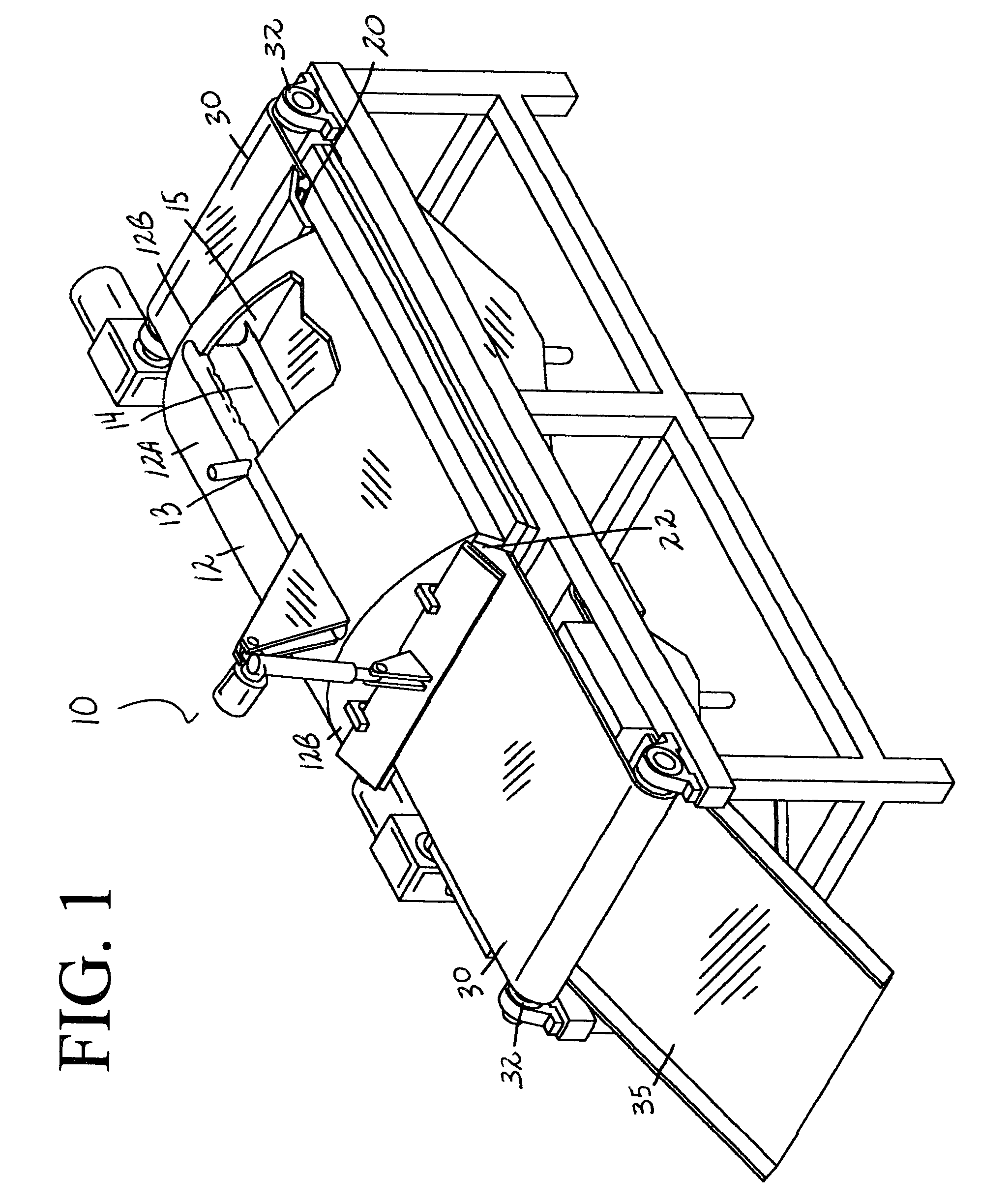
[0013]Keeping the filter belt narrow has several advantages. A long, narrow chamber is much easier to design and build to handle high pressures. An interior four foot filter belt grid requires a lot less structural strength than one eight foot wide. Four foot wide doors are also a lot less likely to warp under pressure than 8 foot doors. Further, uniform distribution of the solids on the filter belt is easier to achieve in a relatively narrow, rectangular chamber.
[0014]For different applications, only the length of the chamber changes; the doors, the belt washer, the rollers, the catch tray, are preferably for an approximate four foot wide filter belt. This all adds up to cost savings plus keeping the system narrow as discussed above also makes it easy to transport.

Problems solved by technology

The higher the force the costlier the equipment plus reliability and leaks become a problem.

Method used


Image

  • System for solid-liquid separation
  • System for solid-liquid separation
  • System for solid-liquid separation

Examples


Embodiment Construction

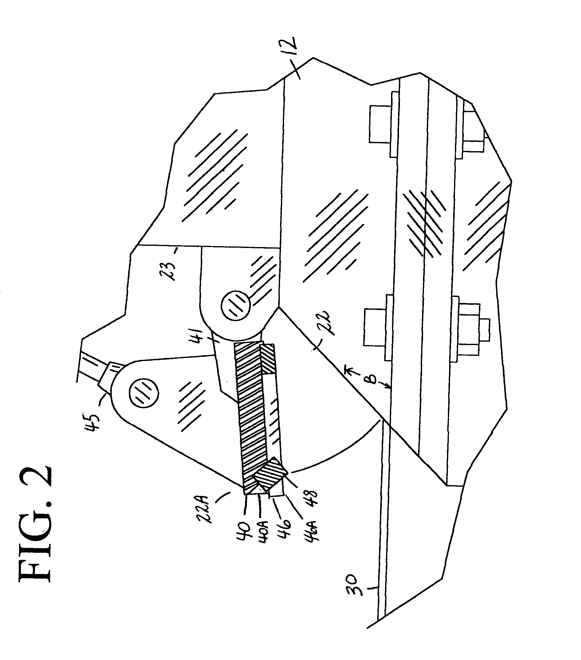
[0021]In accordance with the present invention, a system for solid-liquid separation 10 is disclosed. The system 10 provides semi-continuous filtering of both fibrous materials and particulate materials from slurries, producing the required dry filter cake. The system 10 generally uses a fixed filter chamber member with openings at each end of the chamber for entrance and exit of a filter belt. The openings each include sealing means that require very little force to actuate, or keep closed during the squeeze cycle. In general, the present invention uses an air operated seal to seal the entrance opening for the filter belt, and a special gasket arrangement that seals the exit opening. Linear actuators known in the art are used to close the exit of the chamber for the cake buildup and squeeze cycles, and to open the exit for the discharge of the dry cake. These preferred embodiments save not only in the cost of operating the equipment, but in manufacturing the system 10.

[0022]FIGS. 1...


PUM

PropertyMeasurementUnit
lengthaaaaaaaaaa
areaaaaaaaaaaa
air pressureaaaaaaaaaa

Abstract

A system for use in filtering a slurry using air pressure to squeeze the slurry material and dewatering it. The system including a source of slurry, a chamber, a filter belt that passes through the chamber, a manifold inlet supplying the slurry to a first side of the filter belt to form a uniform moist cake of the filter material, an inlet seal and an outlet seal to seal a belt inlet and a belt outlet formed on the chamber, and a source of the pressurized air selectively applicable to the chamber to dry the moist cake of filtered material.

Description

CROSS REFERENCES TO RELATED APPLICATIONS[0001]U.S. Provisional Application for Patent 60 / 436,233, filed Dec. 26, 2002, with title, “System for Solid-Liquid Separation” which is hereby incorporated by reference. Applicant claims priority pursuant to 35 U.S.C. Par. 119(e)(I).[0002]Statement as to rights to inventions made under federally sponsored research and development: Not applicable.BACKGROUND OF THE INVENTION[0003]1. Field of the Invention[0004]The present invention relates generally to dewatering equipment and more particularly, to a system that semi-continuously filters both fibrous materials and particulate materials from slurries, producing a substantially dry filter cake. The system further deposits the cake in containers, and when required, returns the relatively clean filtrate to be reused.[0005]2. Brief Description of Prior Art[0006]Solid-liquid separation is a major unit operation that exists in almost every flow scheme related to the chemical process industries, ore be...

Claims


Application Information

Patent Timeline
Patent Type & Authority Patents(United States)
IPC IPC(8): B01D33/048B01D29/09B01D33/052
CPCB01D29/09B01D29/82B01D29/84
Inventor TAPP, FLOYD G.
Owner TAPP FLOYD G
Learn More