Continuous vacuum carburizing furnace

Active Publication Date: 2006-04-18
CHUGAI RO CO LTD
View PDF5 Cites 11 Cited by
  • Summary
  • Abstract
  • Description
  • Claims
  • Application Information

AI Technical Summary

Benefits of technology

[0012]The invention has an object to provide a continuous vacuum carburizing furnace used for carburizing the workpieces, the furnace capable of suppressing the production of cementite and adapted for efficient and easy control of the carburized case depth or the surface carbon content of the workpiece.
[0014]In the continuous vacuum carburizing furnace of the invention, the workpiece is heated in the heating chamber under the atmospheric pressure, as described above. This negates the need for reducing the pressure in the heating chamber and hence, the initial and running costs are decreased.
[0015]According to the continuous vacuum carburizing furnace of the invention, a plural number of workpieces from the first conditioning chamber are received by a single carburizing / diffusing chamber, wherein the carburizing and diffusing processes are repeated in plural cycles. Hence, the number of times to open / close the door member is decreased so as to increase the efficiency, as compared with the case where the door members at the plural carburizing / diffusing chambers are opened / closed to sequentially introduce the individual workpieces into the respective carburizing / diffusing chambers for discretely carrying out the carburizing and diffusing processes. Furthermore, the furnace of the invention provides an easy control of the carburizing and diffusing processes.
[0016]The continuous vacuum carburizing furnace of the invention may also be arranged such that the carburizing and diffusing processes are carried out in the first conditioning chamber between the heating chamber and the carburizing / diffusing chamber or in the second conditioning chamber between the carburizing / diffusing chamber and the cooling chamber. Such an arrangement provides an efficient control of the carburized case depth or surface carbon content of the workpiece in a broader range.

Problems solved by technology

However, where the heat time taken by the heating chamber 2, the carburizing time taken by the carburizing chamber 4 and the diffusion time taken by the diffusing chamber 5 are varied greatly in the aforesaid continuous vacuum carburizing furnace, there is a difficulty of continuously introducing the workpieces 1 into the heating chamber 2, the carburizing chamber 4 and the diffusing chamber 5 in sequence.
This leads to inability to accomplish an efficient carburization of the workpieces 1.
However, the heating chamber and the carburizing / diffusing chambers discretely maintained in the reduced pressure entail cost increase.
On the other hand, it is an extremely cumbersome and inefficient operation to open / close a door member to the carburizing / diffusing chamber each time each workpiece in the basket is introduced into each of the carburizing / diffusing chambers in turn and then to subject the workpiece to the carburizing and diffusing processes in the respective carburizing / diffusing chambers.

Method used


Image

  • Continuous vacuum carburizing furnace
  • Continuous vacuum carburizing furnace
  • Continuous vacuum carburizing furnace

Examples


Embodiment Construction

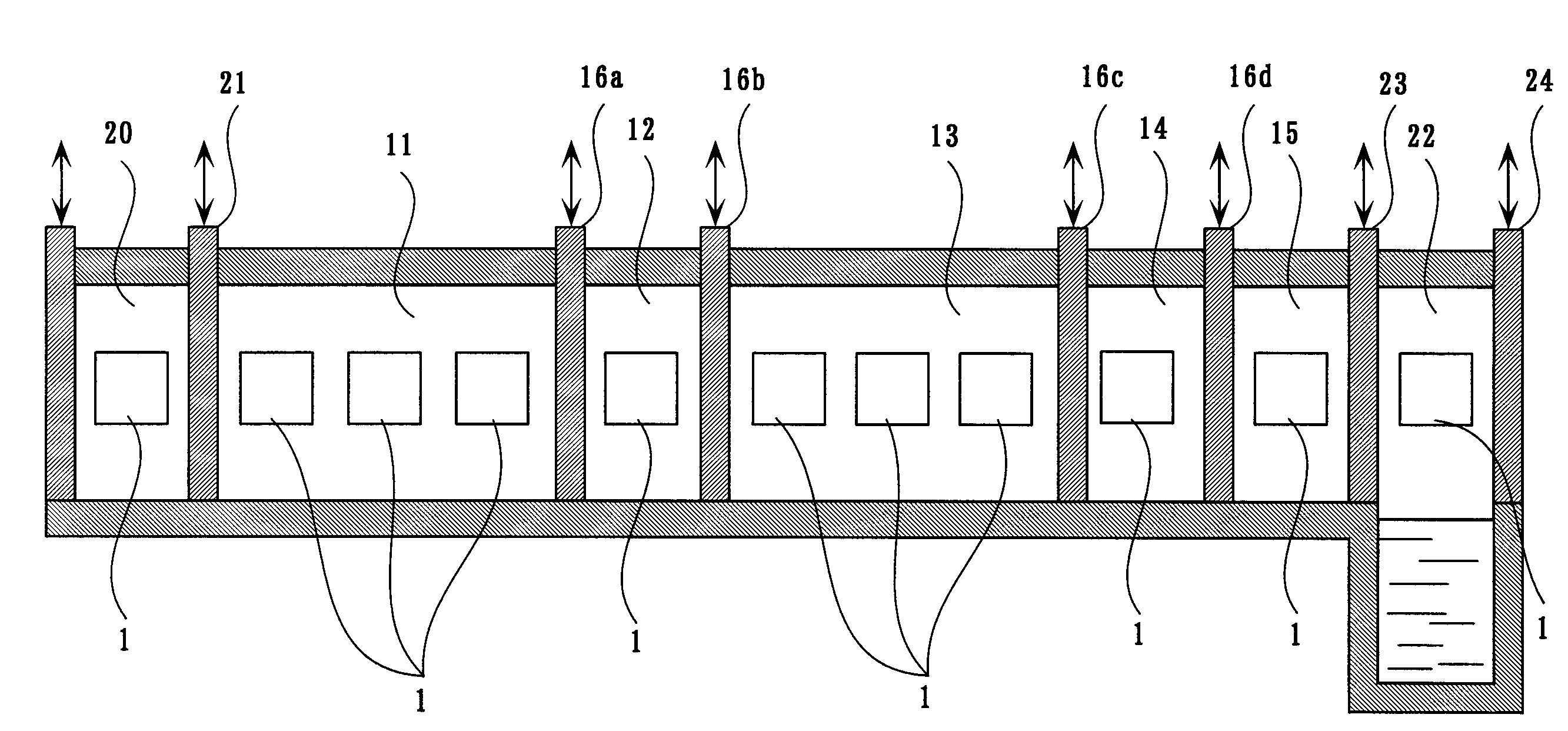
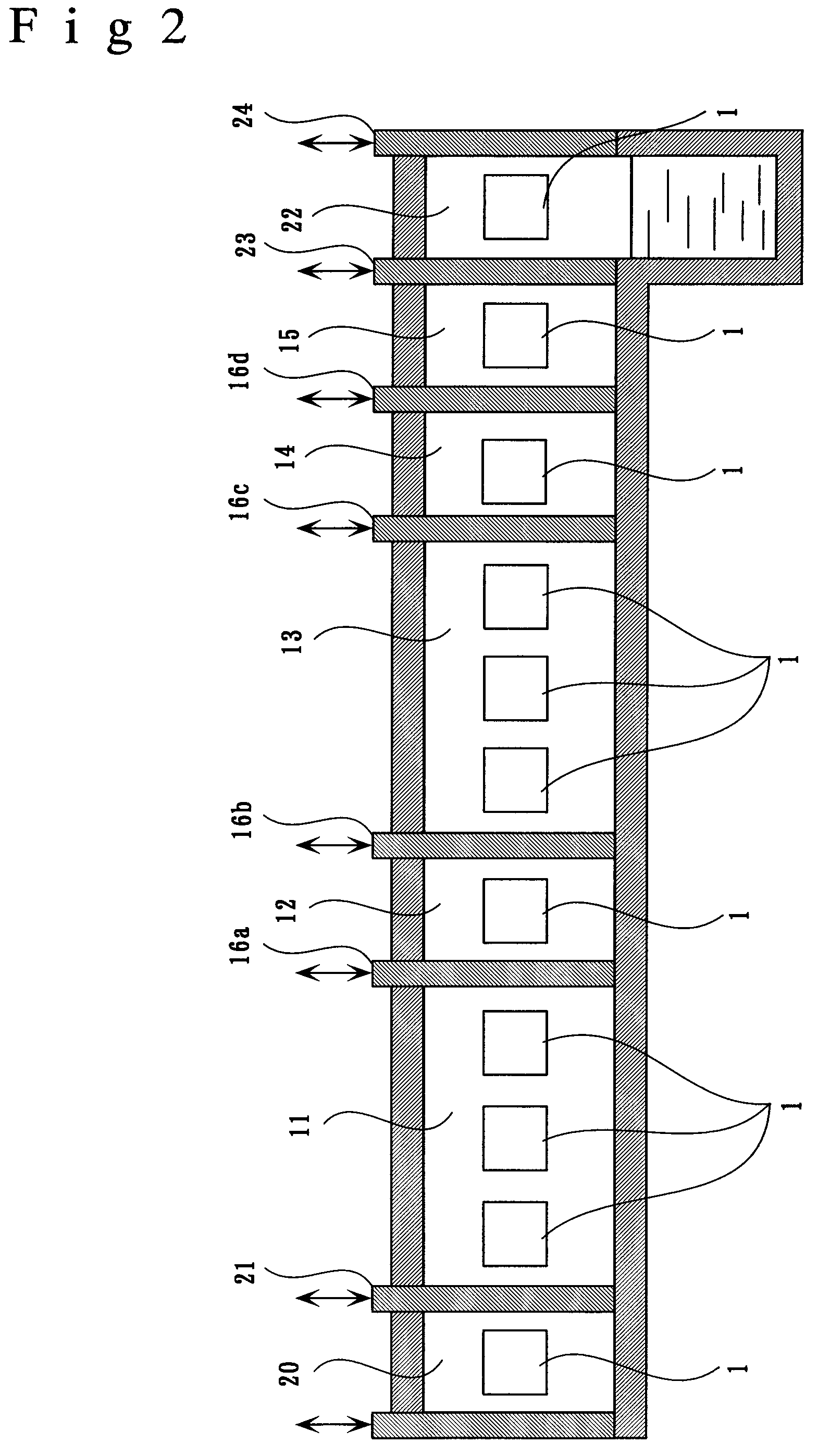
[0020]A continuous vacuum carburizing furnace according to one embodiment of the invention will be specifically described with reference to the accompanying drawings. It is noted that the continuous vacuum carburizing furnace according to the invention is not limited to the following embodiments but may be practiced in modification as required so long such a modification does not depart from the scope of the invention.

[0021]As shown in FIG. 2, the continuous vacuum carburizing furnace according to the embodiment includes: a heating chamber 11 for heating a workpiece 1 under a atmospheric pressure; a first conditioning chamber 12 into which the workpiece 1 heated in the heating chamber 11 is introduced; a carburizing / diffusing chamber 13 receiving plural workpieces 1 from the first conditioning chamber 12 and conducting plural cycles of carburizing and diffusing processes under a reduced pressure; a second conditioning chamber 14 into which the workpiece 1 treated in the carburizing / ...


PUM

PropertyMeasurementUnit
Pressureaaaaaaaaaa

Abstract

A continuous vacuum carburizing furnace of the invention includes: a heating chamber for heating a workpiece under a atmospheric pressure; a first conditioning chamber in which the pressure is reduced from the atmospheric pressure after the receipt of the workpiece from the heating chamber; a carburizing / diffusing chamber receiving plural workpieces from the first conditioning chamber and conducting plural cycles of carburizing and diffusing processes under the reduced pressure; a second conditioning chamber in which the reduced pressure is returned to the atmospheric pressure after the receipt of the workpiece treated in the carburizing / diffusing chamber; and a cooling chamber for cooling the workpiece introduced from the second conditioning chamber under the atmospheric pressure, the furnace further comprising a door member disposed between a respective adjoining pair of the above chambers, the door member opened / closed only when the workpiece is transported from one chamber to another.

Description

BACKGROUND OF THE INVENTION[0001]1. Field of the Invention[0002]The present invention relates to a continuous vacuum carburizing furnace used for carburizing workpieces such as steel parts. More particularly, the invention relates to a continuous vacuum carburizing furnace for continuously performing a sequence of steps including: heating a workpiece; subjecting the heated workpiece to carburizing and diffusing processes under a reduced pressure; and cooling the workpiece, the furnace characterized by suppressing the production of cementite and by providing efficient and easy control of the carburized case depth or surface carbon content of the workpiece.[0003]2. Description of the Related Art[0004]For the purpose of increasing the strength of steel parts, such as of low-carbon steel or low-alloy steel, it has been a conventional practice to subject the steel parts to the carburizing process for diffusing and penetrating carbon thereinto.[0005]A variety of methods are used for carbu...

Claims


Application Information

Patent Timeline
IPC IPC(8): C21D1/773C21D9/00C23C8/22F27B9/02F27B9/04
CPCC21D1/773C21D9/0062C23C8/22F27B9/045F27B9/028F27B9/04F27B9/02
Inventor SHIMOSATO, YOSHIKAZUYOSHIMOTO, SEIJI
Owner CHUGAI RO CO LTD
Why Eureka
Try Eureka