Method and system for monitoring combustion source emissions

a technology of combustion source and monitoring system, applied in the direction of material heat development, instruments, investigating moving fluids/granular solids, etc., can solve the problems of preventing the system from meeting the accuracy requirements, system subject to a number of sources of bias, etc., and achieve the effect of minimizing bias

Inactive Publication Date: 2006-04-18
GENERAL ELECTRIC CO
View PDF23 Cites 14 Cited by
  • Summary
  • Abstract
  • Description
  • Claims
  • Application Information

AI Technical Summary

Benefits of technology

[0005]There is accordingly a need for a CEMS that minimizes bias in the measurement of emission constituent concentration levels generally and N

Problems solved by technology

Current CEMS systems are subject to a number of sources of bias with respect to NOx measurement.
Bias effects in the systems now in

Method used


Image

  • Method and system for monitoring combustion source emissions
  • Method and system for monitoring combustion source emissions
  • Method and system for monitoring combustion source emissions

Examples


Embodiment Construction

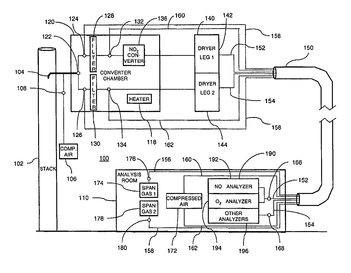
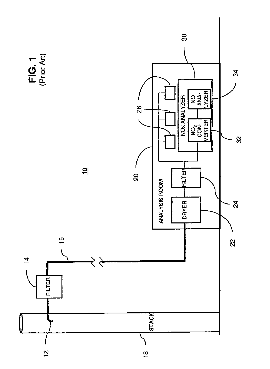
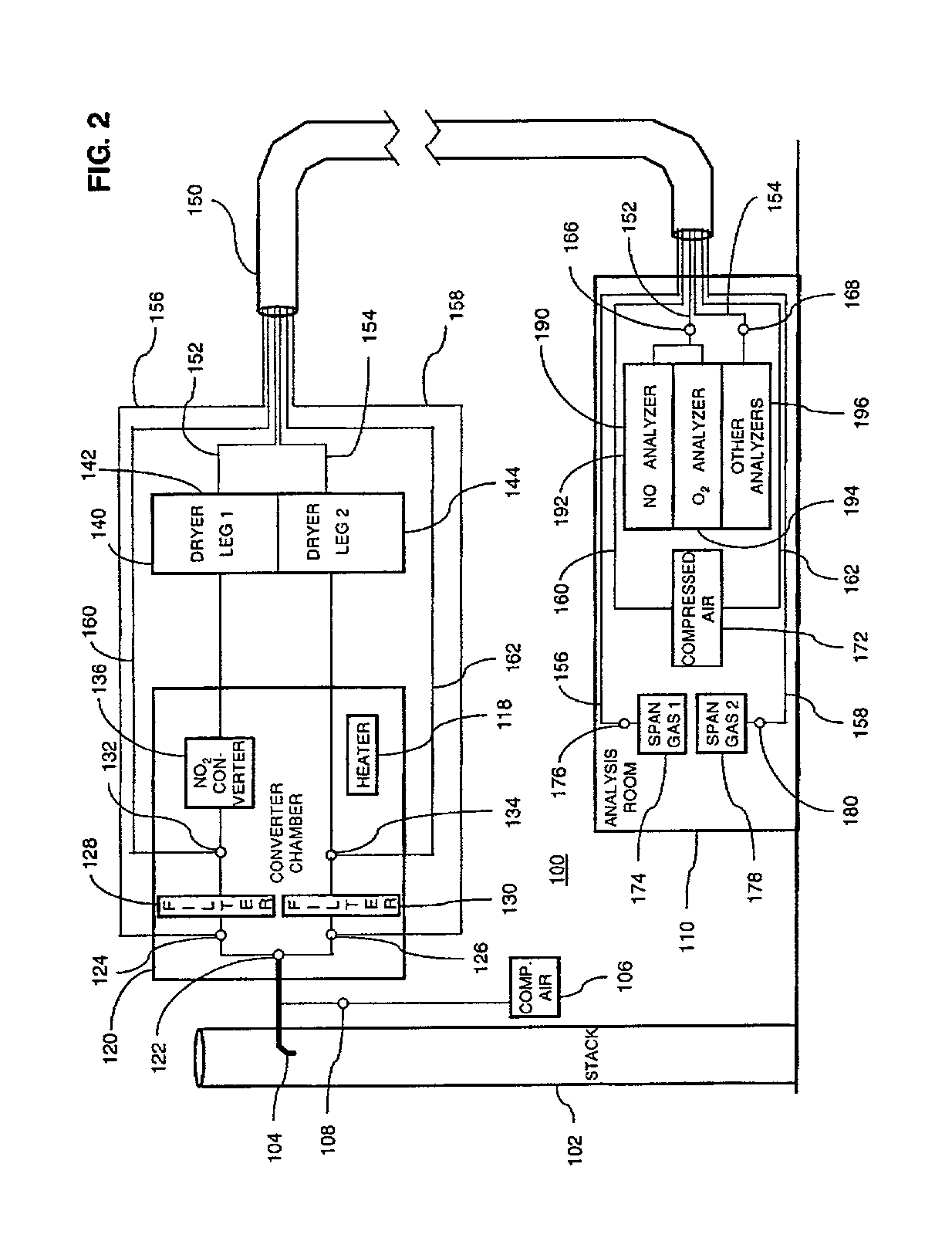
[0019]The present invention provides an emissions monitoring system that minimizes bias effects in the capture and analysis of NOx emissions. The invention also provides a method for routinely monitoring the system to identify changes in measurement bias. FIG. 1 is a schematic illustration of a typical prior art emissions monitoring system 10. In the system 10, multiphase exhaust emissions are drawn from a stack 18 using a sampling device 12. At the outlet of the sampling device 12, the emissions are passed through a filter 14 to remove large particulate matter on the order of 7 microns or greater.

[0020]The resulting sample gas and any remaining particulate matter are then passed through a heated sampling line 16 to a CEMS analysis room 20. The analysis room 20 is typically a small ground level building, trailer or mobile sampling van that houses the analyzers for the various types of emissions that must be assessed. Such a building is typically carefully climate controlled. Upon en...


PUM


Abstract

A method and system for determining a concentration level of NOx in an exhaust stream from a combustion source. The method comprises capturing sample gas from the exhaust stream using a sampling device. NO2 in the sample gas is converted to NO by passing the sample gas through a catalytic NO2 converter. The method also comprises removing water from the sample gas by passing the sample gas through a dryer and determining a sample gas NO concentration level. The step of converting NO2 is performed at a temperature above the dew point temperature of the sample gas.

Description

BACKGROUND OF THE INVENTION[0001]This invention relates to the measurement of air pollutant emissions from gas turbines, boilers, process heaters, furnaces and other combustion sources. More particularly, the invention relates to a continuous emission monitoring method and system that minimizes bias in the measurement of air pollutant emissions.[0002]Power plants and other users of combustion sources such as gas-fired turbines are required to keep emissions of certain exhaust constituents at or below specified levels. Continuous emission monitoring systems (CEMS) are required in order to assure on a continuous basis that the mandated levels are maintained. Over time, however, improved methods of minimizing emissions have evolved and emissions standards have become more stringent. CEMS systems are therefore required to consistently measure lower and lower concentrations of pollutant emissions.[0003]As the maximum allowable concentrations of air pollutants have decreased, the effects ...

Claims


Application Information

Patent Timeline
IPC IPC(8): G01N33/00G01N33/22G01N21/76G01N1/22G01N1/24G01N21/35G01N21/85
CPCG01N1/2258G01N33/0037Y10T436/255G01N2001/2261G01N2001/227Y10T436/177692Y10T436/186Y10T436/25125Y10T436/17Y10T436/207497Y10T436/204998Y10T436/25Y10T436/20Y10T436/25375Y10T436/208339Y10T436/178459Y10T436/25875Y10T436/205831Y10T436/179228G01N1/24Y02A50/20
Inventor LANIER, WILLIAM STEVENENGLAND, GLENN
Owner GENERAL ELECTRIC CO
Why Eureka
Try Eureka