
Sensor detecting reflected light and method for its manufacture

Active Publication Date: 2006-04-18
SARTORIUS LAB INSTR GMBH & CO KG
View PDF15 Cites 83 Cited by
  • Summary
  • Abstract
  • Description
  • Claims
  • Application Information

AI Technical Summary

Benefits of technology

[0009]It is an object of the invention to provide an arrangement for optical reflected-light sensors with planar glass panes that are integrated in a hybrid manner, and a method for producing such sensors, in connection with which the suppression of the parasitic optical trans-coupling from the emitter to the receiver can be simply and effectively accomplished.
[0011]The sensor for detecting reflected light as defined by the invention has a glass pane with light-absorbing areas. The shape and position of these areas allow suppressing the optical “crosstalk” from the light emitter to the photo receiver. These barriers can be produced in an advantageous manner from an ultraviolet (UV)-sensitive glass by means of micro-technical methods.

Problems solved by technology

Such parasitic trans-coupling, which is referred to also as optical “crosstalk”, is a general problem posed by this sensor principle and determines to a large extent the achievable resolution and the usable dynamic range.
The drawback afflicting this solution is that the surface of the sensor is generally no longer planar and consists of different materials.
Furthermore, due to the manufacturing conditions, it is not possible to reduce the distance between the components of the emitter and the components of the receiver as desired.

Method used


Image

  • Sensor detecting reflected light and method for its manufacture
  • Sensor detecting reflected light and method for its manufacture
  • Sensor detecting reflected light and method for its manufacture

Examples


Embodiment Construction

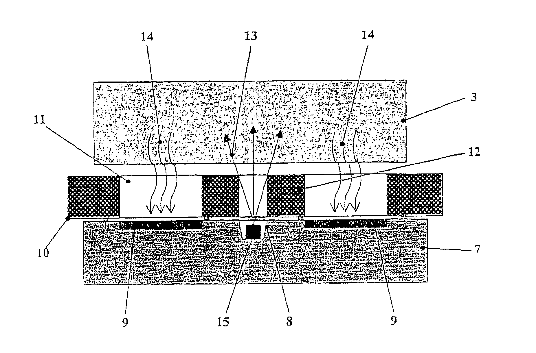
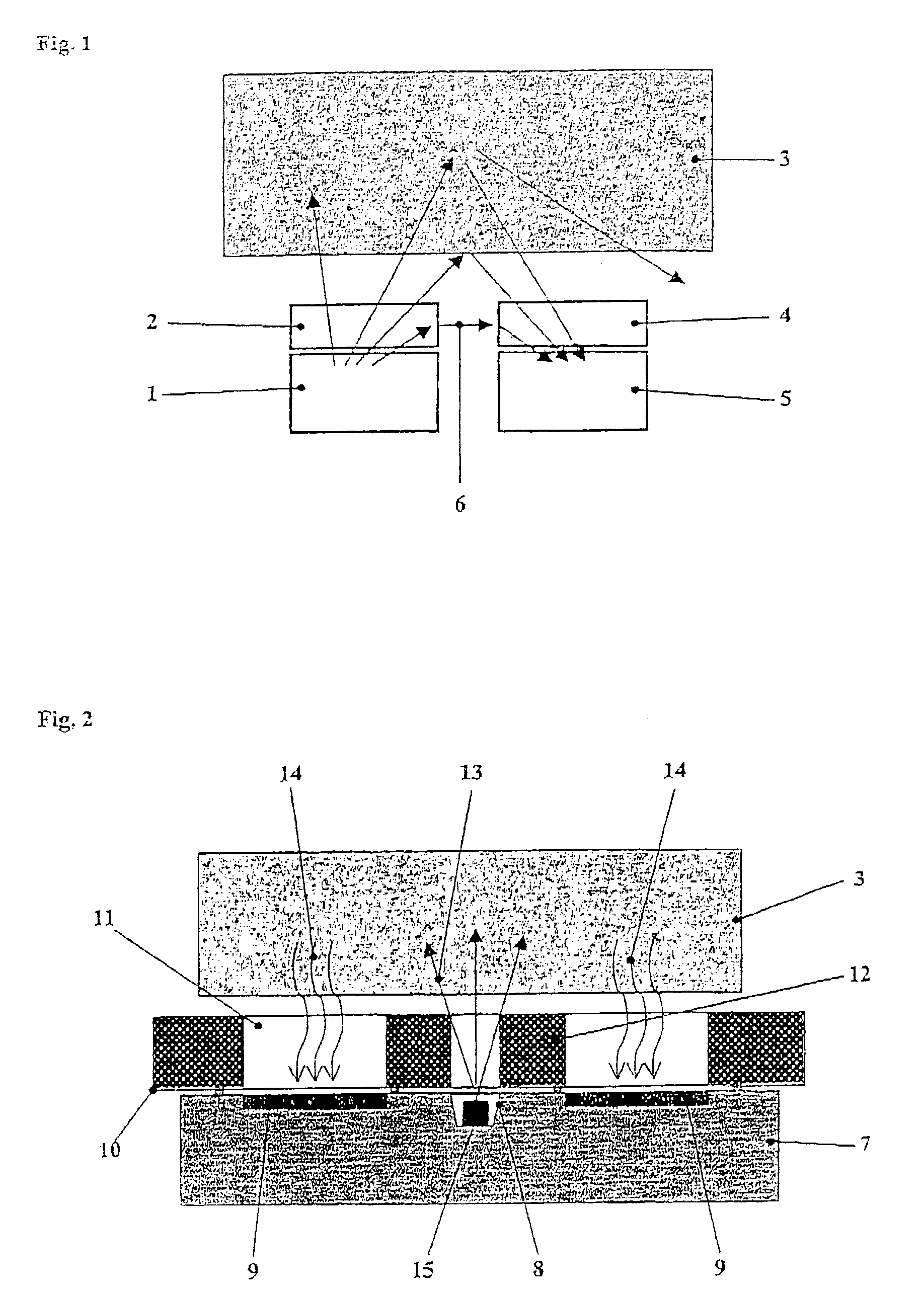
[0022]Referring now in detail to the drawings, FIG. 1 shows the basic structure of a hybrid sensor for detecting reflected light. The radiation emitted by the light emitter 1 penetrates the transparent protective layer 2 of the emitter, is then reflected on the object 3 being measured, and partly passes through the protective layer 4 of the receiver and to the optical receiver 5. Between transparent protective layers 2 and 4, an undesirable component of the emitted light passes via the coupling path 6 directly from the light emitter to the receiver 5.

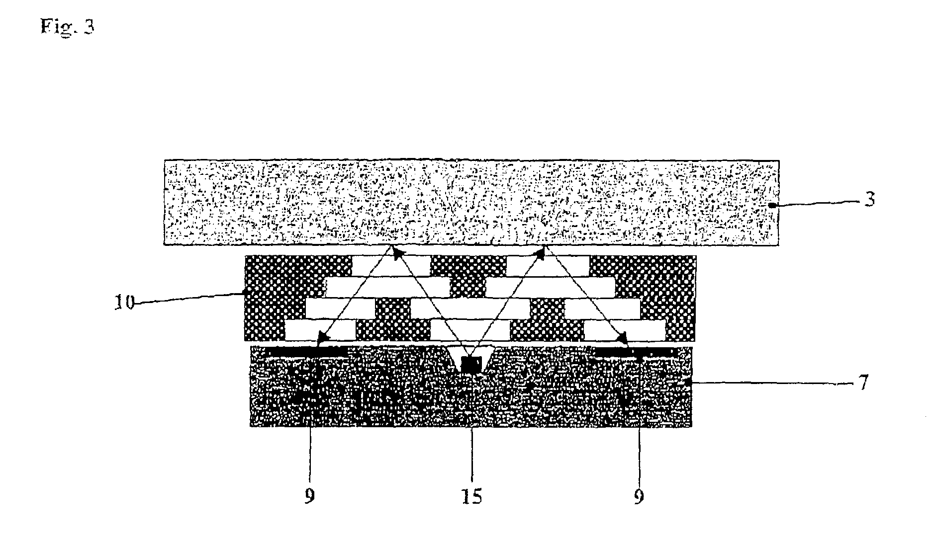
[0023]FIG. 2 shows a reflected-light sensor that is integrated in a hybrid manner by a cross-sectional view, where the protective layer of glass 10 has been produced from UV-sensitive glass. Such UV-sensitive types of glass are commercially available and are offered in the market, for example under the trade name FOTURAN® by the firm SCHOTT Glaswerke of Mainz, Germany. UV-sensitive glasses can be changed from the originally transparent ...


PUM


Abstract

A reflected-light sensor includes a light emitter for emitting radiation onto an object to be measured and an optical receiver for receiving the reflected radiation from the object. The sensor includes a carrier for the light emitter and the optical receiver and a glass layer arranged on the carrier. The glass layer has transparent areas arranged above the light emitter and the optical receiver and light absorbing areas located in between.

Description

CROSS REFERENCE TO RELATED APPLICATIONS[0001]Applicant claims priority under 35 U.S.C. §119 of German Application No. 102 09 931.6 filed Mar. 7, 2002.[0002]1. Field of the Invention[0003]The present invention relates to a sensor for detecting reflected light, and to a method for producing a reflected-light sensor, in connection with which the radiation emitted by a light emitter is reflected or redeflected on an object being measured, and received by an optical receiver. The radiation passes through transparent protective layers that are arranged on a carrier (or substrate).[0004]2. The Prior Art[0005]Optical sensors for detecting reflected light are employed in large numbers in many areas in the field of the controlling and regulating technology. They are frequently used in the form of so-called reflection-light scanners. The radiation emitted by a light emitter passes through a transparent protective layer, is remitted by the object being measured, and then is partially received i...

Claims


Application Information

Patent Timeline
IPC IPC(8): G01D5/34H01L25/18G01D5/26G01S7/481G01S17/04H01J3/14H01J5/16H01L31/0232H01L31/167H01L31/18
CPCG01S17/026G01S7/4811G01S17/04
Inventor ROMHILD, DIETER
Owner SARTORIUS LAB INSTR GMBH & CO KG
Learn More