Power transfer switch assembly

Inactive Publication Date: 2006-04-18
DYNAGEN TECH
View PDF19 Cites 34 Cited by
  • Summary
  • Abstract
  • Description
  • Claims
  • Application Information

AI Technical Summary

Benefits of technology

[0007]It is an object of the present invention to obviate or mitigate at least one of the disadvantages described above. More specifically, it is an object of the present invention to provide a power transfer switch for switching power supplies to a

Problems solved by technology

Among the problems typically confronting a user of electricity wishing to install a back-up power supply is the installation complexity of a traditional transfer switch.
This is an expensive process as it must be performed by electrical professionals and it is a ti

Method used


Image

  • Power transfer switch assembly
  • Power transfer switch assembly
  • Power transfer switch assembly

Examples


Example

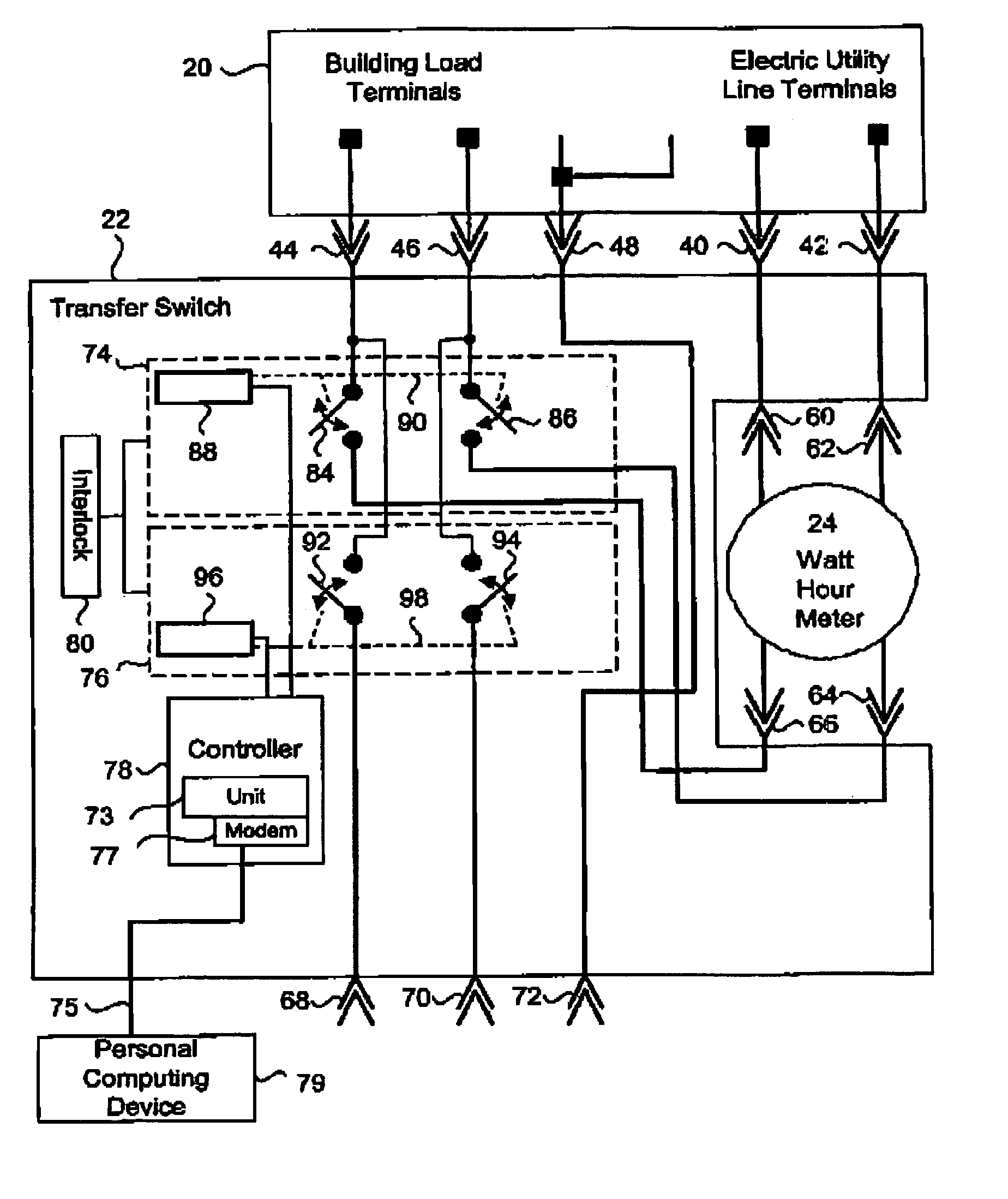
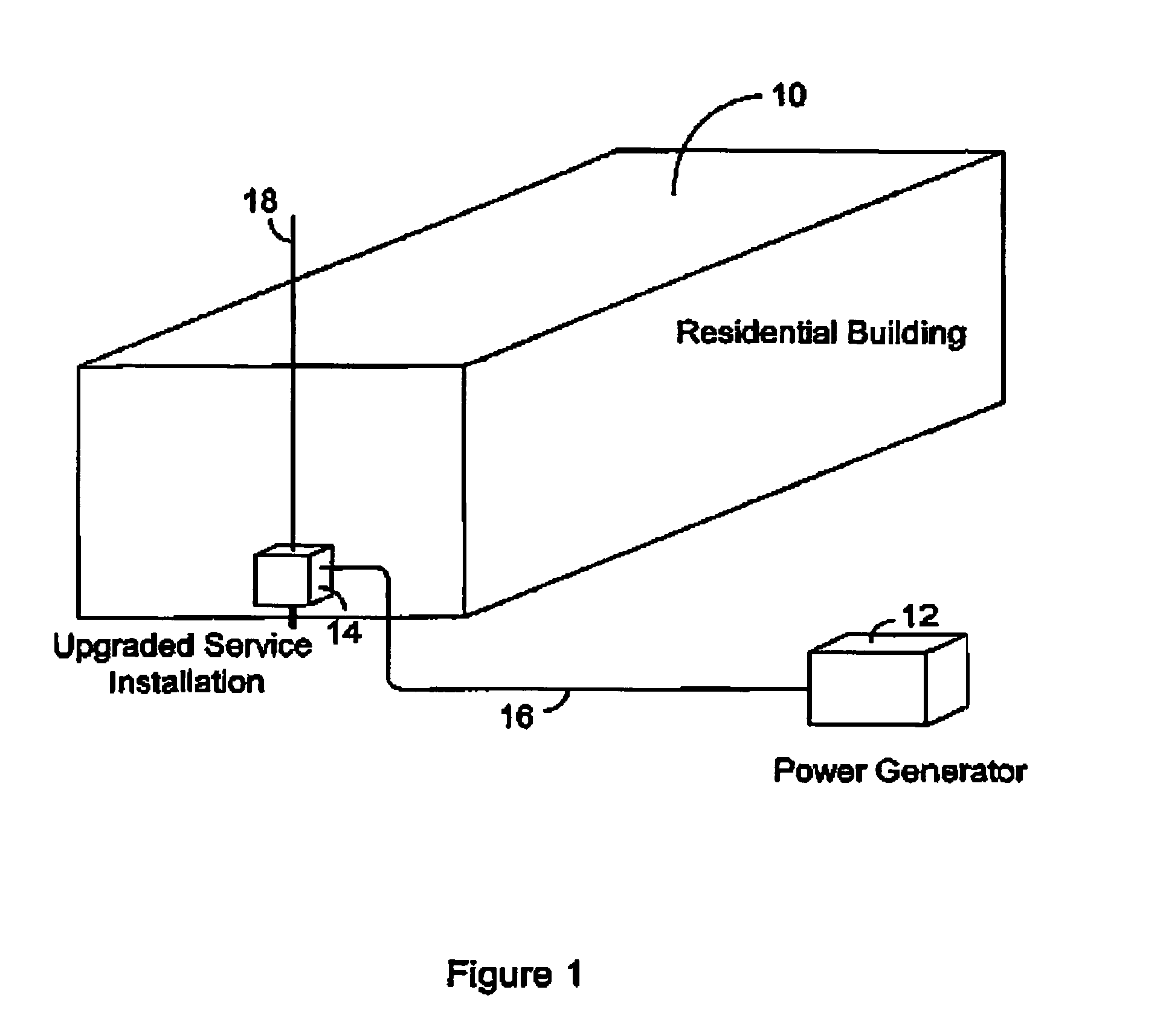
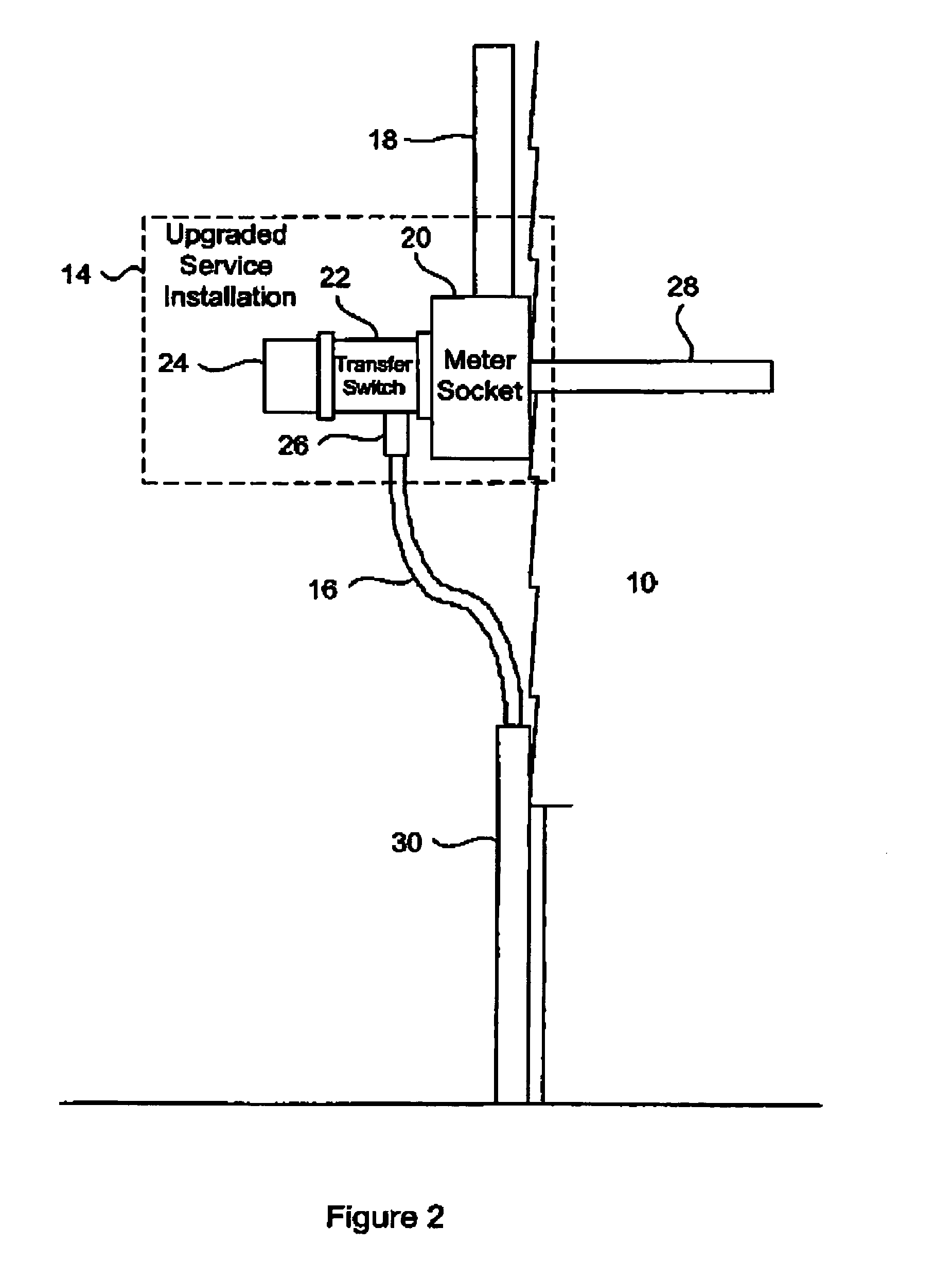
[0020]A modularly attachable transfer switch assembly for operative connection to two power sources and a power load is disclosed. The transfer switch can be quickly and easily installed upon existing service installations, and includes one power switch for selectively connecting a electrical utility power supply to the power load of a structure, such as a building for example, and a second power switch for selectively connecting an emergency power supply to the power load of the building. The transfer switch includes a mechanical interlock operatively connected to both the power switches for physically preventing both the power switches from assuming simultaneous ON positions, and a controller for controlling the emergency power supply and the transfer switches. Upon loss or disturbance in the electrical utility power supply, the transfer switch will automatically activate the emergency power supply, disconnect the utility power supply from the building and connect the emergency po...


PUM


Abstract

A modularly attachable transfer switch assembly for operative connection to two alternate power sources and a power load is disclosed. The transfer switch can be quickly and easily installed upon existing electrical meters and therefore does not require modifications to existing electrical wiring systems. The transfer switch includes one power switch for selectively connecting a electrical utility power supply to the power load of a structure, such as a building for example, and a second power switch for selectively connecting an emergency power supply to the power load of the building. The transfer switch includes a mechanical interlock operatively connected to both the power switches for physically preventing both the power switches from assuming simultaneous ON positions, and a controller for controlling the emergency power supply and the transfer switches. The transfer switch is enclosed within a casing adapted for connection between a watt-hour meter and a meter socket of existing service installations for simple installation of the transfer switch.

Description

[0001]This application claims priority from U.S. provisional patent application Ser. No. 60 / 312,765, filed Aug. 17, 2001.FIELD OF THE INVENTION[0002]The present invention relates to electrical switching assemblies. In particular, the present invention relates to transfer switch assemblies for interconnecting power to a building from two alternate power supplies.BACKGROUND OF THE INVENTION[0003]Customers of electric utility companies often desire a back-up electrical power supply during a power outage. Typically, such a back-up is provided by an alternate power supply such as a fuel-fired engine-driven power generator, an inverter, solar cells or fuel cells, for example. A common method used is the installation of a power generator which is interfaced with an automatic or manual transfer switch that is capable of simultaneously disconnecting the electric utility (mains) power supply and connecting the alternate power supply to the facility loads.[0004]Manual transfer switches usually...

Claims


Application Information

Patent Timeline
IPC IPC(8): H01H35/00H02J3/38H02J9/06H02J9/08
CPCH02J9/06H02J9/066H02J9/08H02J9/061H01H2300/018H02J2009/068H02J9/068
Inventor WAREHAM, PAULLANGHAM, DAVID
Owner DYNAGEN TECH
Why Eureka
Try Eureka