
Apparatus for refreshing batteries

a rechargeable battery and battery technology, applied in the direction of charging/discharging, secondary cell servicing/maintenance, transportation and packaging, etc., can solve the problem that the discharge circuit provided within the charging device cannot be effectively used, and achieve the effect of reliability eliminating the memory effect of the rechargeable battery

Inactive Publication Date: 2006-04-18
MAKITA CORP
View PDF26 Cites 35 Cited by
  • Summary
  • Abstract
  • Description
  • Claims
  • Application Information

AI Technical Summary

Benefits of technology

[0007]It is, accordingly, an object of the present teachings to provide improved apparatus that can effectively perform the refresh process.
[0011]Therefore, when the battery pack is connected directly to the battery charger, the batteries of the battery pack can only be connected to the charging circuit, and the battery pack can only be charged. Alternatively, when the adapter is connected to the battery charger, and the battery pack is connected to the adapter, the batteries of the battery pack can be optionally connected to either the charging circuit or the discharging circuit. Consequently, the battery pack can be charged or the refresh process can be performed thereon. Accordingly, if one adapter is provided for a plurality of battery chargers and battery packs, the adapter can effectively perform the refresh process.
[0019]In another aspect of the present teachings, the refresh process of the first period or the second period may equally well be set such that discharging is repeated a plurality of times (twice, for example) therein. This plurality of discharges can reliably eliminate memory effects in the rechargeable battery. In this case, the control circuit may cause only one discharging to be performed per attachment of the battery pack. Since a plurality of discharges is not performed per one attachment, less time elapses between the attachment of the battery pack and the completion of charging. However, it is possible that a plurality of discharges is performed neither in the first period nor the second period. This has the consequence that the control circuit does not cause the refresh process to be performed within these periods. If, within the first period (or the second period), a plurality of discharges is not performed (that is, if the rechargeable battery is not attached a plurality of times to the battery charger with the adapter interposed therebetween), the refresh process may be preferably performed once again in the second period (or the first period).

Problems solved by technology

Therefore, the discharging circuit provided within the charging device cannot be effectively used.

Method used


Image

  • Apparatus for refreshing batteries
  • Apparatus for refreshing batteries
  • Apparatus for refreshing batteries

Examples


Embodiment Construction

Detailed Representative Embodiment

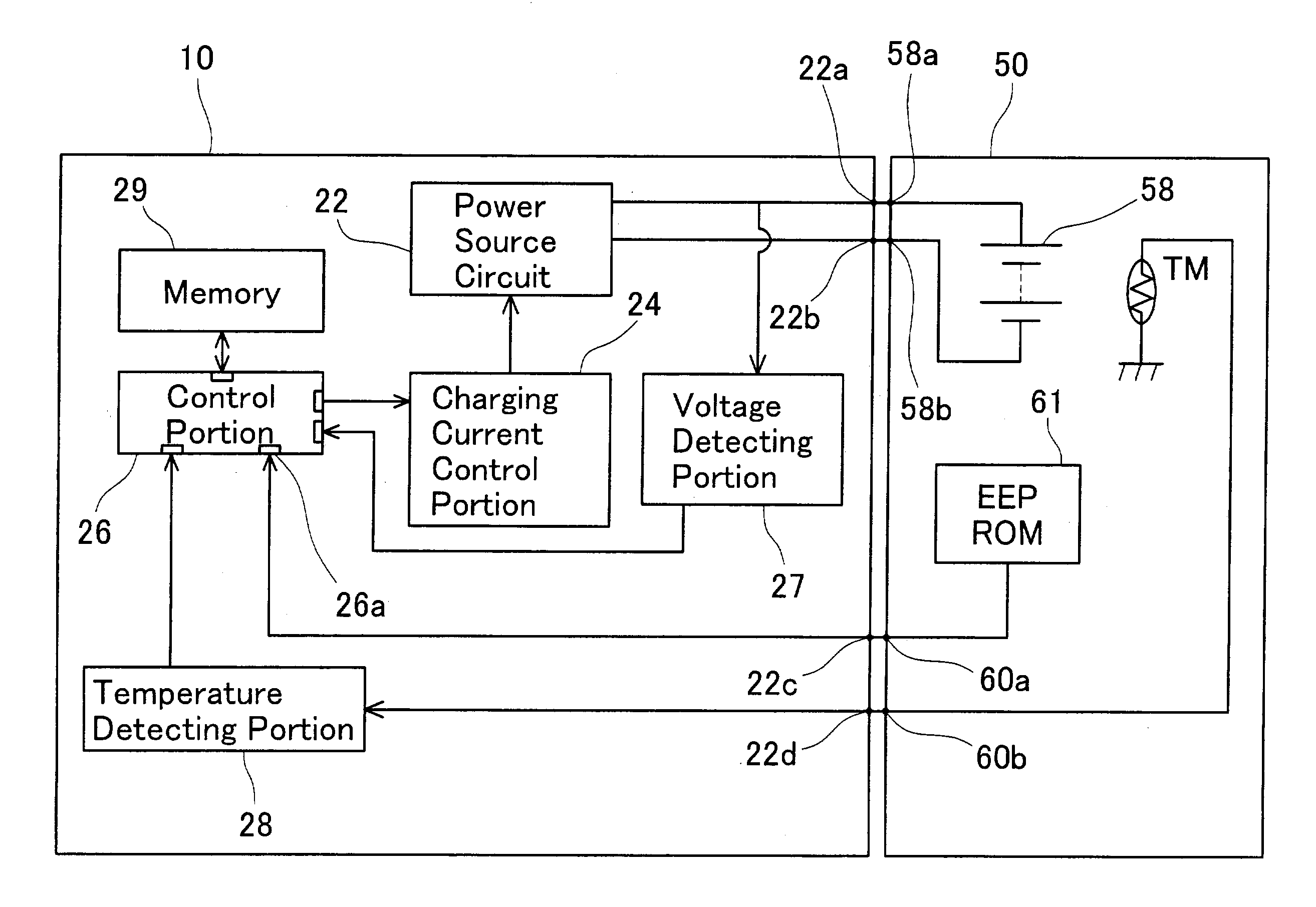
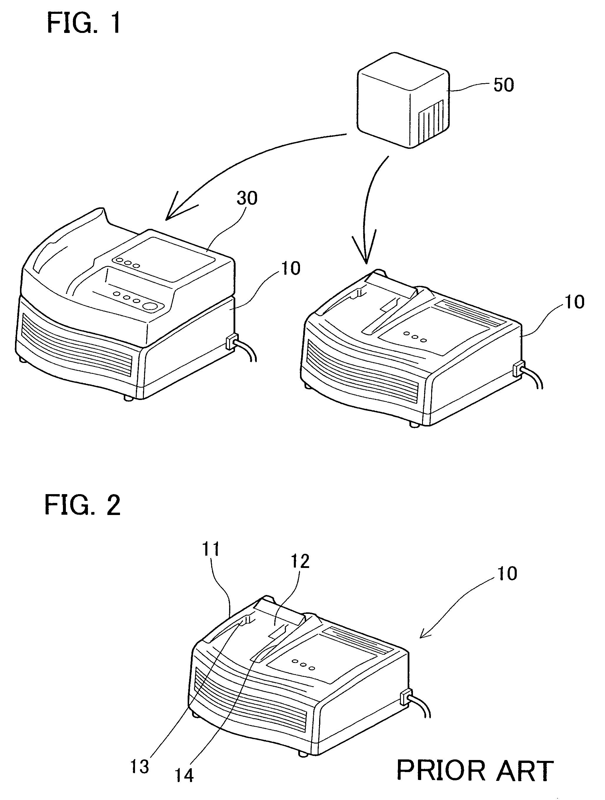
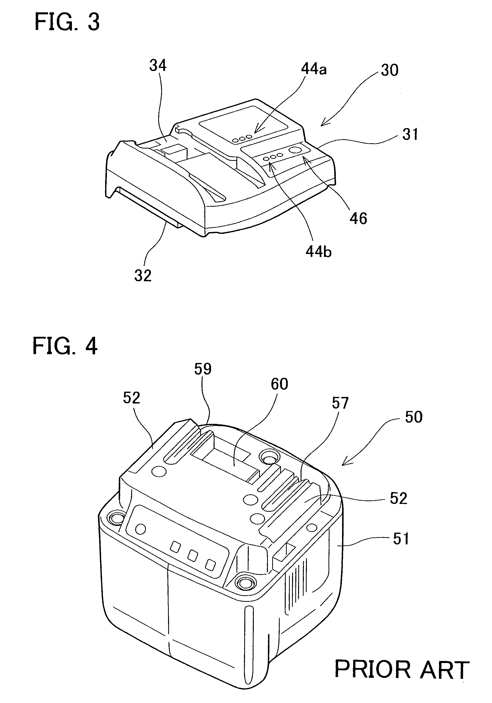
[0038]FIG. 1 shows a detailed representative embodiment of a battery charger 10, an adapter 30 and a battery pack 50 according to the present teachings. FIG. 2 shows the external appearance of battery charger 10, FIG. 3 shows the external appearance of adapter 30 and FIG. 4 shows the external appearance of battery pack 50. FIG. 5 shows a block diagram that identifies functions of battery charger 10 when it is directly coupled to battery pack 50. FIG. 6 shows a block diagram that identifies functions of battery charger 10 when it is coupled to battery pack via adapter 30.

[0039]As shown in FIG. 1, battery charger 10 can be coupled to either adapter 30 or battery pack 50. When adapter 30 is coupled to battery charger 10 (the state shown on the left in FIG. 1), battery pack 50 can be coupled to battery charger 10 via adapter 30. When adapter 30 is not coupled to battery charger 10 (the state shown on the right in FIG. 4), battery pack 50 can be directly...


PUM

PropertyMeasurementUnit
chargesaaaaaaaaaa
number of chargesaaaaaaaaaa
poweraaaaaaaaaa

Abstract

Battery charger (10) may include a power source circuit (22) for charging rechargeable batteries (58) when a battery pack (50) is connected directly to the battery charger or is connected thereto with an adapter (30) interposed therebetween. The adapter may include a discharging circuit (42) for discharging the rechargeable batteries. The adapter may also include a switch (48) for alternatively connecting the rechargeable batteries with the discharging circuit or the charging circuit of the battery charger. The battery pack may have a memory (61) storing a flag indicating whether a refresh process is required. The adapter may further include a control portion (41) for controlling the switch. When the battery pack has been connected to the battery charger via the adapter, the control portion may preferably controls the switch on the basis of the flag stored in the memory of the battery pack.

Description

[0001]This application claims priority to Japanese patent application number 2002-84382, the contents of which are hereby incorporated by reference.BACKGROUND OF THE INVENTION[0002]1. Field of the Invention[0003]The present invention relates to techniques for eliminating memory effects of rechargeable batteries (e.g., a nickel metal hydride battery, a nickel cadmium battery).[0004]2. Description of the Related Art[0005]Japanese Laid-open Patent Publication No. 7-143680 describes an appliance that is powered by a rechargeable battery (i.e., secondary battery). The known appliance has a charging device that is disposed within a housing of the appliance. The charging device includes a discharging circuit and a counter. The counter is utilized to count the number of charges of the battery. If the value of the counter is below a predetermined value when the battery is to be charged, the battery is charged, and the counter adds “1”. On the other hand, if the value of the counter reaches a...

Claims


Application Information

Patent Timeline
Patent Type & Authority Patents(United States)
IPC IPC(8): H02J7/00H02J7/04H01M10/44
CPCH02J7/0075H02J7/0044H02J7/0047H02J7/0069H02J7/0048
Inventor SAKAKIBARA, KAZUYUKIMURAMATSU, TOMOOOKABAYASHI, HISAKAZU
Owner MAKITA CORP
Learn More