
Externally clocked electrical fuse programming with asynchronous fuse selection

a technology of asynchronous fuse selection and external clock, applied in the direction of static storage, digital storage, instruments, etc., can solve the problems of difficult control of the blowing process, difficult to blow fuses in parallel, and time-consuming and laborious problems

Inactive Publication Date: 2006-04-18
POLARIS INNOVATIONS
View PDF13 Cites 19 Cited by
  • Summary
  • Abstract
  • Description
  • Claims
  • Application Information

AI Technical Summary

Problems solved by technology

The requirement for a well defined blow voltage makes it difficult to blow fuses in parallel.
This means that each fuse that actually blows changes the conditions to which the other fuses are subjected, which make it very difficult to control the blow process.
However, test time and costs become an issue when fuses are to be blown serially.
Moreover, it is very unlikely that every single redundant memory element is needed for replacing defective normal memory elements.
Accordingly, because a DRAM may contain thousands of fuses, serial fuse programming may add significant time to the length of a test flow.
However, adding an address decoder just for addressing the fuses is generally cost prohibitive because such a decoder with associated address wiring consumes chip area.
One problem of this second method is that programming cycles during which no fuse is blown (called empty programming cycles) waste time.
Moreover, because a large percentage of the fuses of a chip do not need to be blown, most of the programming time is wasted on empty programming cycles, which is undesirable.

Method used


Image

  • Externally clocked electrical fuse programming with asynchronous fuse selection
  • Externally clocked electrical fuse programming with asynchronous fuse selection
  • Externally clocked electrical fuse programming with asynchronous fuse selection

Examples


Embodiment Construction

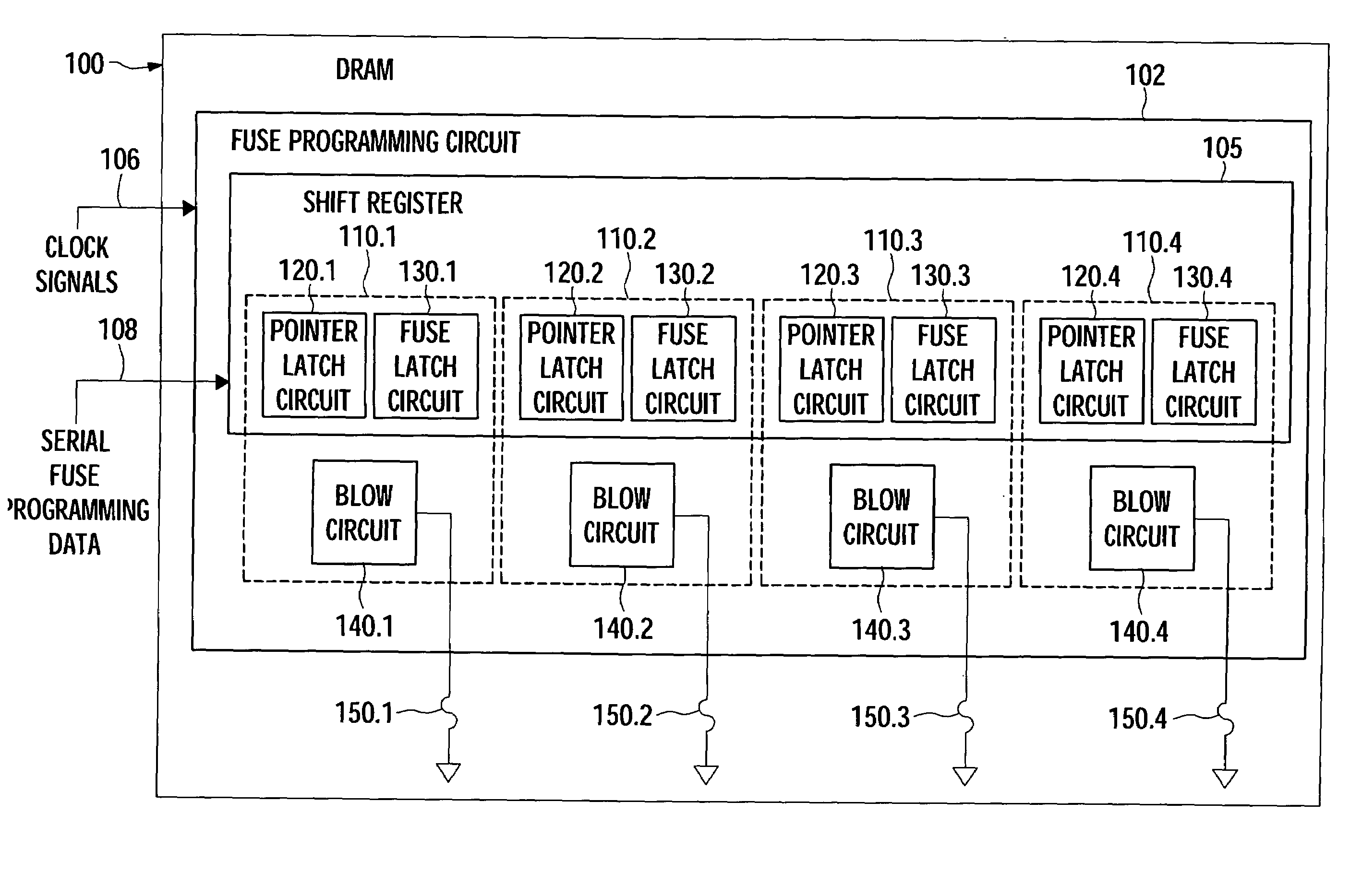
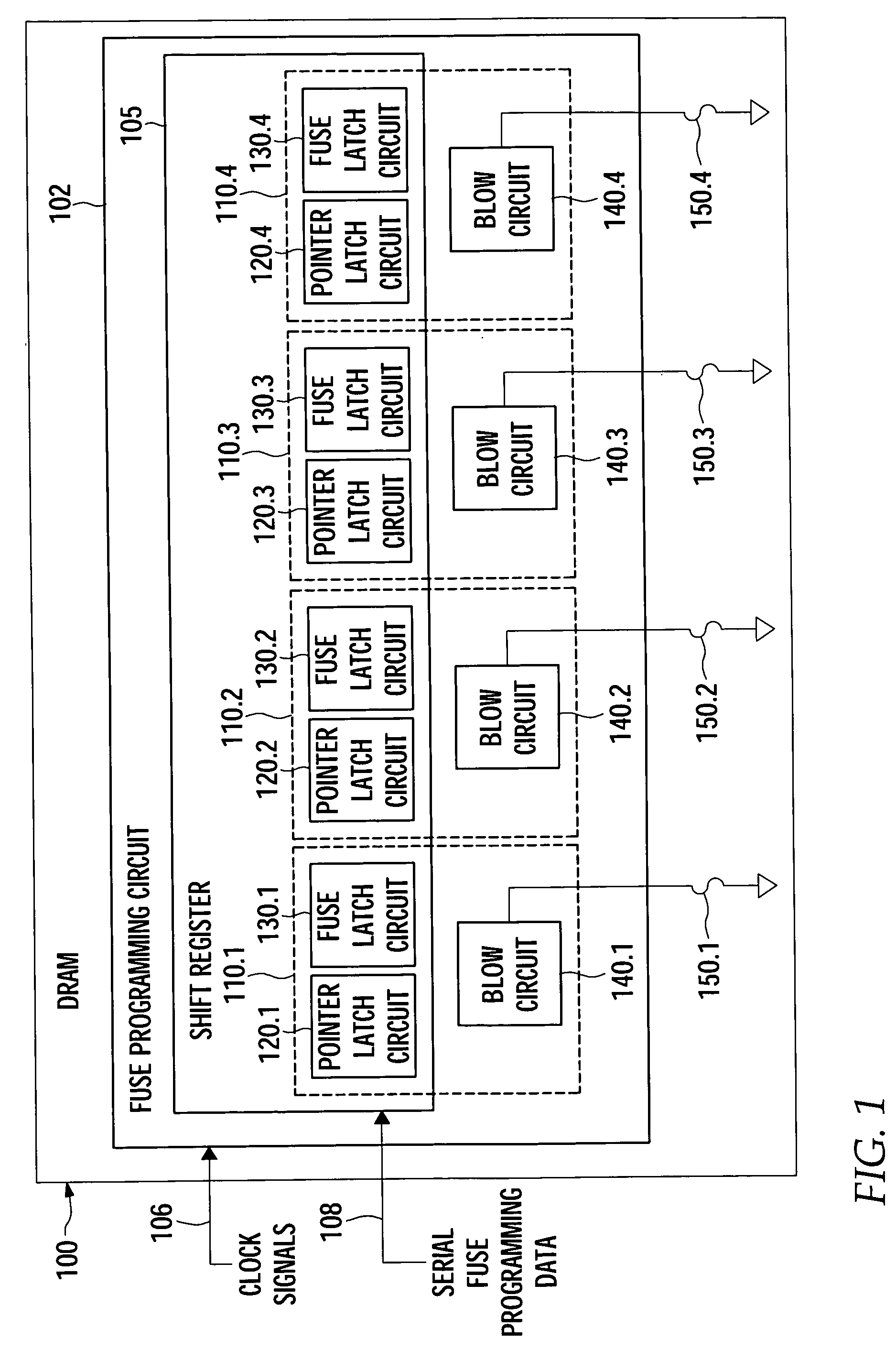
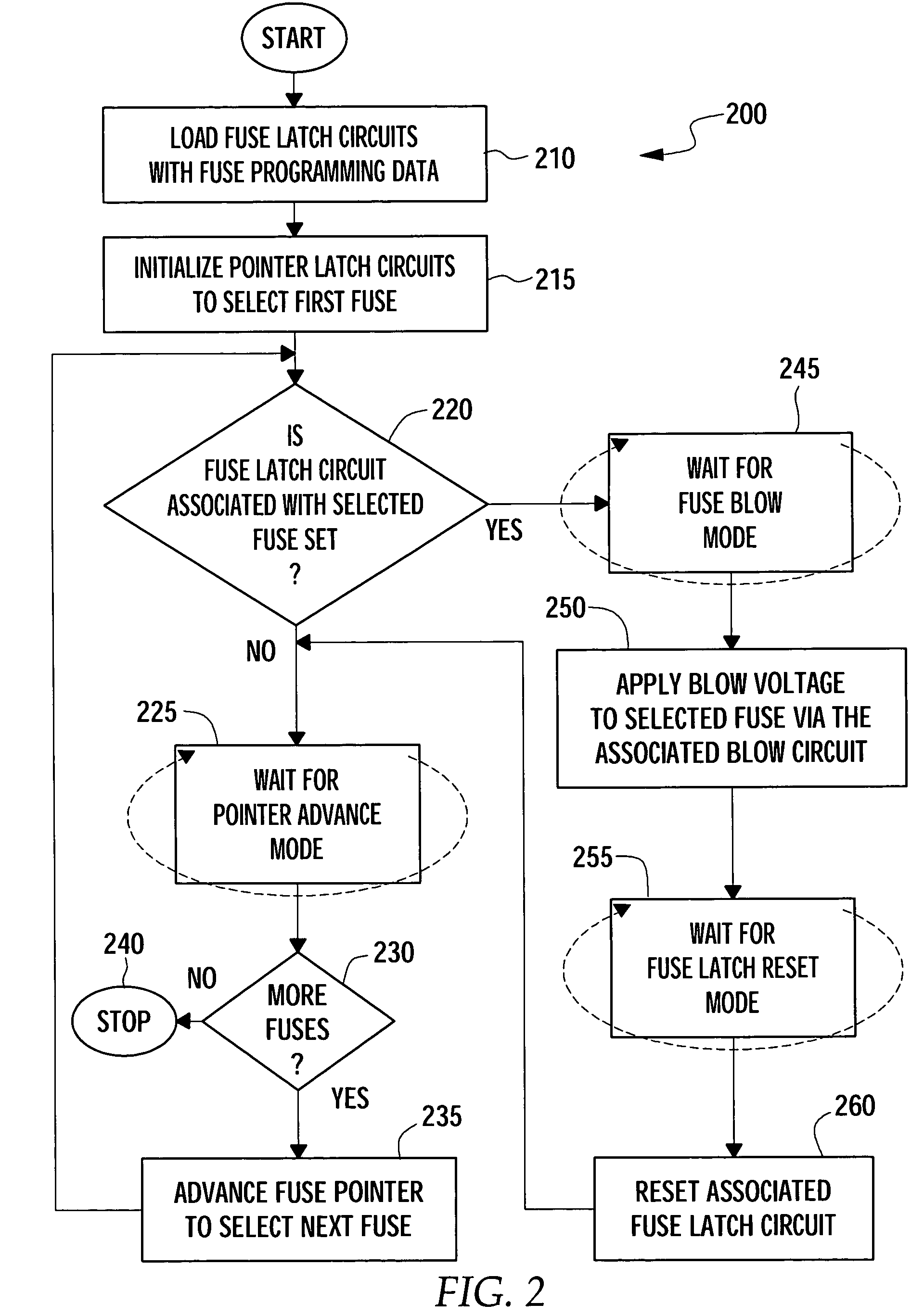
[0026]Embodiments are provided in which a method and an apparatus for the programming of fuses are described. A fuse pointer is advanced to point to (i.e., select) the fuses sequentially. When the fuse pointer reaches (i.e., points to) a fuse that is not to be blown, the fuse pointer automatically and asynchronously (e.g. not synchronized to a programming clock signal) skips the fuse. On the other hand, when the fuse pointer reaches a fuse that is to be blown, the fuse pointer stops and the fuse is blown synchronously (e.g., synchronized to the programming clock signal). After blowing the fuse, the fuse pointer advances to the next fuse and the process described above repeats, until the last fuse is programmed. The programming (or blow) clock signal may be generated from an external clock signal, which may be easily varied to ensure adequate exposure time to the blow voltage. By controlling the exposure time with an external clock signal, relatively long exposure times may be achiev...


PUM


Abstract

Embodiments are provided in which a method and an apparatus for sequentially programming electrical fuses are described. A fuse pointer is advanced to point to (i.e., select) the fuses sequentially. When the fuse pointer reaches (i.e., points to) a fuse that is not to be blown, the fuse pointer automatically and asynchronously (e.g. not synchronized to a programming clock signal) skips the fuse. On the other hand, when the fuse pointer reaches a fuse that is to be blown, the fuse pointer stops and the fuse is blown synchronously (e.g., in response to the programming clock signal). After the blow, the fuse pointer advances to the next fuse and the process described above repeats, until the last fuse is programmed. A fuse latch circuit associated with the blown fuse may be optionally reset prior to advancing the fuse pointer.

Description

CROSS-REFERENCE TO RELATED APPLICATIONS[0001]This application claims priority to U.S. provisional patent application Ser. No. 60 / 427,207, filed Nov. 18, 2002, and is related to the commonly-owned, U.S. patent application Ser. No. 10 / 716,381 entitled DUAL-PURPOSE SHIFT REGISTER, filed herewith, both of which are herein incorporated by reference in their entirety.BACKGROUND OF THE INVENTION[0002]1. Field of the Invention[0003]The present invention generally relates to the programming of fuses, and more particularly to sequential programming of electrical fuses.[0004]2. Description of the Related Art[0005]Electrical fuses are commonly used on integrated circuits (ICs) for the programming of manufacturer settings. For example, common uses are the enabling of redundancy on memory ICs, the trimming of certain parameters to compensate for process variations, and the customization of the IC's external specification and behavior. Typically, an electrical fuse is comprised of either a narrow ...

Claims


Application Information

Patent Timeline
Patent Type & Authority Patents(United States)
IPC IPC(8): G11C7/00G11C8/00G11C11/24G11C17/18G11C19/00
CPCG11C17/18G11C19/00
Inventor HOFFMANN, JOCHENHOKENMAIER, WOLFGANG
Owner POLARIS INNOVATIONS
Learn More